
Comparator circuit having latching behavior and digital output sensors therefrom

Active Publication Date: 2010-02-25
HONEYWELL INT INC
View PDF7 Cites 43 Cited by
  • Summary
  • Abstract
  • Description
  • Claims
  • Application Information

AI Technical Summary

Benefits of technology

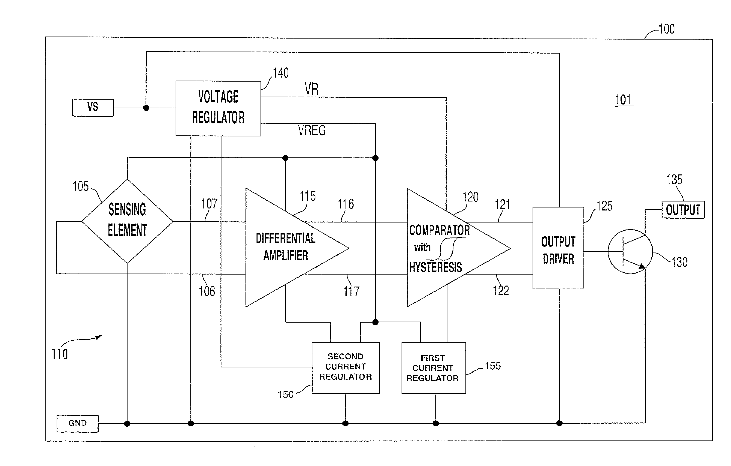
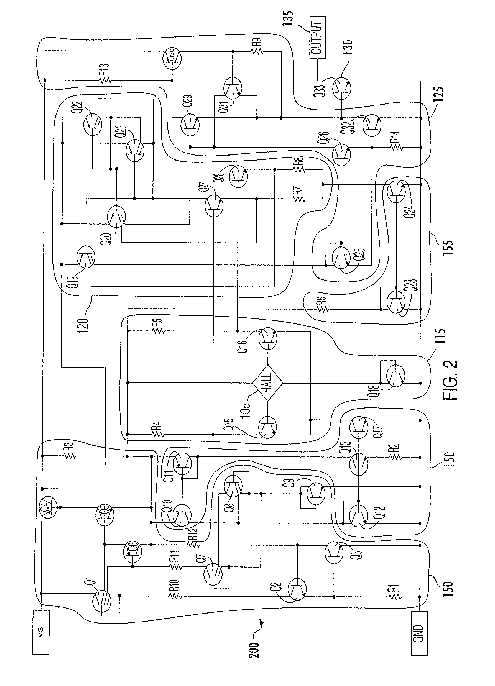
[0009]Embodiments of the present invention describe new comparator circuitry operable to receive a differential input signal and provide a differential output signal and digital output sensors therefrom. The comparator circuits described herein utilize internal positive feedback to provide the hysteretic relationship between the sensed binary signal levels, thus avoiding the need in conventional designs for a pair of Schmitt triggers or the need for a feedback loop to the amplifier stage that precedes the comparator. Comparators according to embodiments of the invention also provide new temperature compensation and supply voltage rejection circuitry. These aspects lower power requirements and reduce die size, thereby reducing the cost of the sensor. Comparators according to embodiments of the invention can be embodied as balanced circuitry that comprises two identical half circuits (and thus has full symmetry).

Problems solved by technology

The trade-offs in using precision on-chip voltage regulation is larger die size / cost and additional supply current.
When the comparator switches, the states of the current-mirror loads are reversed (e.g. one saturated and one off) so that the feedback current, hence the offset voltage, is switched from one side of the input stage to the other, thereby providing hysteresis that results in noise margin between the sensed binary states.

Method used


Image

  • Comparator circuit having latching behavior and digital output sensors therefrom
  • Comparator circuit having latching behavior and digital output sensors therefrom
  • Comparator circuit having latching behavior and digital output sensors therefrom

Examples


Embodiment Construction

[0019]The present invention is described with reference to the attached figures, wherein like reference numerals are used throughout the figures to designate similar or equivalent elements. The figures are not drawn to scale and they are provided merely to illustrate the instant invention. Several aspects of the invention are described below with reference to example applications for illustration. It should be understood that numerous specific details, relationships, and methods are set forth to provide a full understanding of the invention. One having ordinary skill in the relevant art, however, will readily recognize that the invention can be practiced without one or more of the specific details or with other methods. In other instances, well-known structures or operations are not shown in detail to avoid obscuring the invention. The present invention is not limited by the illustrated ordering of acts or events, as some acts may occur in different orders and / or concurrently with o...


PUM


Abstract

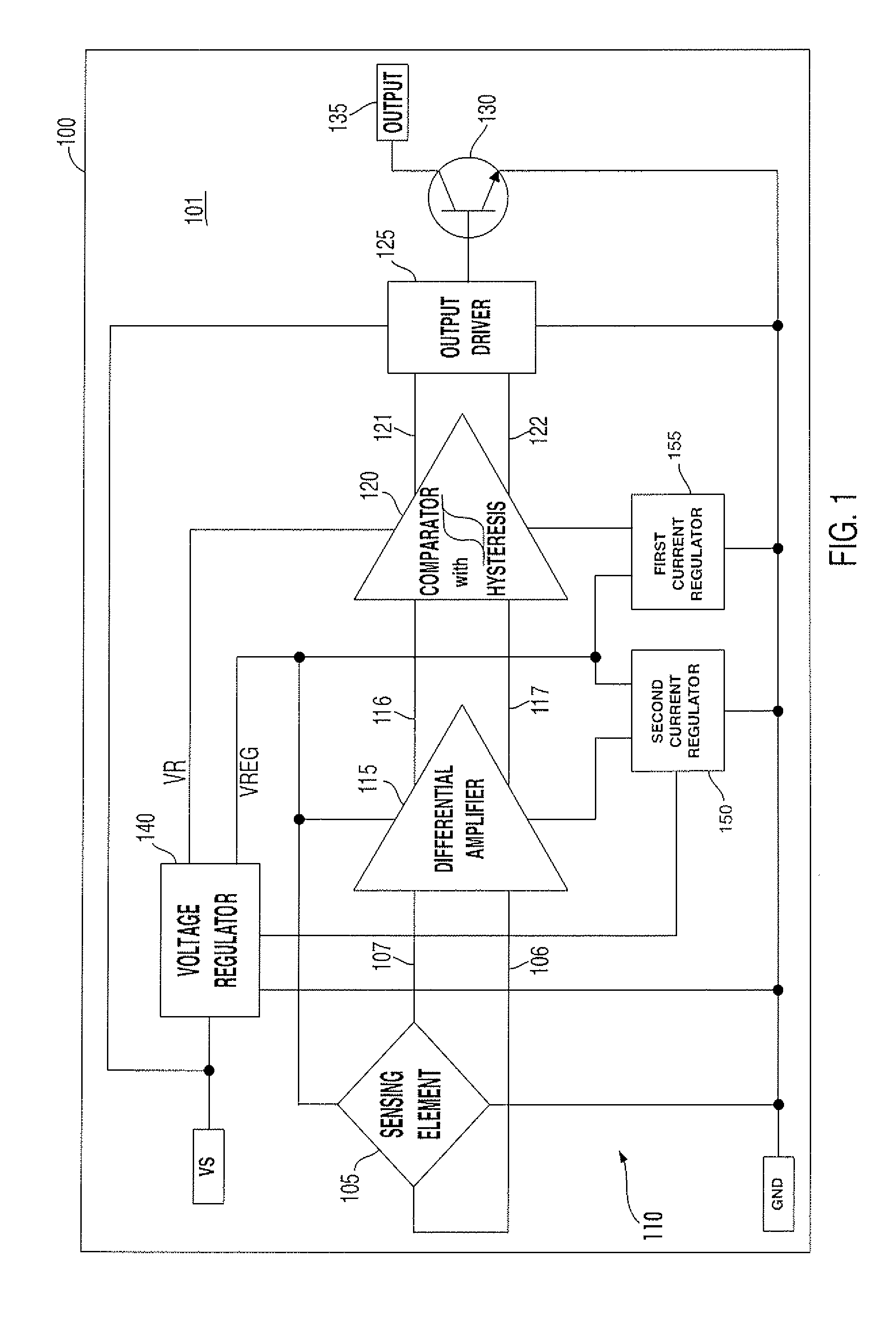
A digital output sensor (110) includes a sensing structure (105) including at least one sensing element. The sensing structure (105) outputs a differential sensing signal (106, 107). An integrated circuit (100) includes a substrate (101) including signal conditioning circuitry for conditioning the sensing signal (106, 107). The signal conditioning circuitry includes a differential amplifier (115) coupled to receive the sensing signal and provide first and second differential outputs (116, 117), and a comparator (120) having input transistors (Q27, Q28) coupled to receive outputs from the differential amplifier. The comparator (120) also includes first and second current-mirror loads (Q19 / Q21 and Q22 / Q20) coupled to the input transistors (Q27, Q28) in a cross coupled configuration to provide hysteresis, wherein the first and second current-mirror loads provide differential drive currents (121,122). An output driver (125) is coupled to receive the differential drive currents (121, 122). An output stage (130) includes at least one output transistor which is coupled to the output driver for providing a digital output for the sensor. A voltage regulator (140) is coupled to receive a supply voltage (VS) and output at least one regulated supply voltage (VREG), wherein the regulated supply voltage is coupled to the sensing structure (105), the differential amplifier (115) and the comparator (120).

Description

FIELD OF THE INVENTION[0001]Embodiments of the invention relate to digital output sensors, and more particularly integrated circuit-based digital output sensors.BACKGROUND[0002]Sensors are used to sense a variety of different quantities. For example, the quantity or parameter to be sensed can be a magnetic field, a current, a temperature, a pressure or a position. Commonly used sensing structures include piezoelectric elements positioned on or formed in a flexible diaphragm for sensing pressure, electrically conducting or semiconducting elements based on the Hall effect, magnetoresistance or variable reluctance structures for sensing magnetic fields.[0003]Hall sensors are one form of magnetic field sensor that can be manufactured at low cost particularly when embodied as an integrated (monolithic) sensor. When a current-carrying conductor or semiconducting Hall element is placed into a magnetic field, a voltage will be generated orthogonal to the direction of both the current and th...

Claims


Application Information

Patent Timeline
IPC IPC(8): G01B7/00G01R19/00
CPCH03K19/18G01R15/207
Inventor KILIAN, WAYNE
Owner HONEYWELL INT INC
Learn More