Ultra-short slip and packing element system

a technology of packing elements and ultra-short slips, applied in the field of downhole tools, can solve the problems of high cost, high cost, and high cost of packing elements, and achieve the effects of reducing milling time, low cost, and reducing milling tim

Inactive Publication Date: 2011-04-21
OILTOOL ENG SERVICES
View PDF3 Cites 90 Cited by
  • Summary
  • Abstract
  • Description
  • Claims
  • Application Information

AI Technical Summary

Benefits of technology

[0012]This invention provides an improved packer for cased wells or for a tubular member positioned inside of casing. The invention includes a number of features that overcome the above mentioned problems. A very short and simple packer design, with features that increase overall packer reliability, is created by effectively combining synergies of the cone, slip and seal elements to work in unison.
[0014]The packer can be ready modified to serve several applications: 1) A hydraulic setting cylinder can be added so the packer can be run as part of the casing or tubing; 2) the packer can utilize a fixed frangible disc or a flapper device to serve as a bridge plug, frac plug, or a preferred title, a “Frac Disc”. The materials of the packer can be optimized to reduce mill-out time. Mill-out time is greatly reduced due to the very short length of the packer, around 4″, so expensive composite materials aren't necessarily required, 3) a seal bore can easily be attached to the packer body, 4) since the slip system creates a metal-to-metal interface with the I.D. of the casing, the packer can readily be adapted to a high pressure and temperature well environment, 5) the packer can address applications as simple as low cost plug and abandonment to highly complex applications in hostile environment wells, and 6) the packer, due to it's short length, is ideal for incorporating “control line pass-thru” for intelligent well completions.

Problems solved by technology

Problems with prior art packers, in some cases, can be the excessive length of the packers since all of the above combined systems require length.
Typical packers, as described above, tend to have mill-out problems because the packer parts tend to spin within the engaged slips.
The mill operation becomes very inefficient because the packer parts spin with the rotation of the milling tool.
Another problem is that the slip system is loaded through the packing element system without a fully supported packing element to prevent extrusion.
Extrusion of the packing element system reduces stored energy in the slip system thus allowing the slip system to disengage, especially during pressure reversals, the casing and in turn cause packer slippage and seal failure.
The built-in extrusion gap can be a problem and is commonly the primary mode of seal system failure at higher temperatures and pressures.
This is because the elastomers and backup devices tend to move into the extrusion gaps.
When this movement occurs, the stored energy is lost in the seal system and the seal engagement is jeopardized to the point of seal failure.
It is a problem in that due to the incremental contact on the I.D. of the casing, high non-uniform stresses in the casing wall can cause deformation or even failure of the casing wall.
These breaking problems can reduce the performance and reliability of the packer.

Method used


Image

  • Ultra-short slip and packing element system
  • Ultra-short slip and packing element system
  • Ultra-short slip and packing element system

Examples


Embodiment Construction

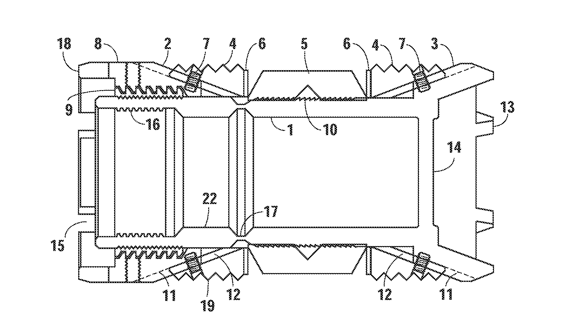
[0021]With reference to FIG. 1, a schematic of the present invention shows a 180 degree lengthwise cross-section of the packer. A mandrel 1 has a running thread 16 with a tension or shear parting point, or connection, 17 located below the running thread. The mandrel 1 may be shortened by more than one means at point 17, i.e., any type of shear, tension, or locking device that can be separated in a fashion to shorten the mandrel. A setting tool (not shown) is made up to running thread 16 in order to convey the packer into the well. A millable, frangible or disintegrable disc 14 is a fluid barrier and is part of mandrel 1 or can be attached and sealed to mandrel 1 in some fashion. Cone surface 3 is shown of the O.D. of mandrel 1. Slip segments 4 are expandable by sliding up coned surfaces at 2 and 3. Seal 5, commonly known as a packing element, is located between slip segments 4 and extrusion barriers 6. Seal 5 is compressed and expanded between slip segments 4.

[0022]The slip segments...


PUM


Abstract

A packer device, with a commercial name called “Frac Disc” includes an interior packer mandrel and radially surrounding cone, slip and seal system that seals and engages the surrounding casing or other tubular member. The cones expand the slip system and the slips compress and expand the seal system, simultaneously. The slip system provides a means for supporting the seal system when pressure is applied from above or below the packer. The close proximity of the seal and slip system in combination with a separating packer body provides for a very short packer, or a “minimum material packer”, that offers lower cost, higher performance, and if required, faster mill-out.

Description

CROSS-REFERENCE TO RELATED APPLICATION[0001]This application is related in subject matter to application Ser. No. 12 / 653,155 filed Dec. 9, 2009 entitled “Subterranean Well Ultra-Short Slip and Packing Element System”, Gregg W. Stout, inventor.BACKGROUND OF THE INVENTION[0002]1. Field of the Invention[0003]This invention relates to downhole tools for oil and gas wells and similar applications and more particularly to improved well packers.[0004]2. Description of Prior Art[0005]Well packers are used to form an annular barrier between well tubing or casing, to create fluid barriers, or plugs, within tubing or casing, or the control or direct fluid within tubing or casing. Packers may be used to protect tubulars' from well pressures, protect tubulars' from corrosive fluids or gases, provide zonal isolation, or direct acid and frac slurries into formations.[0006]Typical well packers consist of a packer mandrel. Radially mounted on the packer mandrel is a locking or release mechanism, a p...

Claims


Application Information

Patent Timeline
Patent Type & Authority Applications(United States)
IPC IPC(8): E21B33/12
CPCE21B33/129E21B33/1204
Inventor STOUT, GREGG W.
Owner OILTOOL ENG SERVICES
Why Eureka
Try Eureka