Pneumatic hand tool rotational speed control method and portable apparatus

Inactive Publication Date: 2011-04-21
FORGUES SYLVAIN +1
View PDF7 Cites 811 Cited by
  • Summary
  • Abstract
  • Description
  • Claims
  • Application Information

AI Technical Summary

Benefits of technology

[0024]According to the present invention, there is provided a control device which maintains the required operating speed of the rotary peening tool.
[0025]Maintaining the speed of the

Problems solved by technology

The titanium dust produced during grinding can be

Method used


Image

  • Pneumatic hand tool rotational speed control method and portable apparatus
  • Pneumatic hand tool rotational speed control method and portable apparatus
  • Pneumatic hand tool rotational speed control method and portable apparatus

Examples


Example

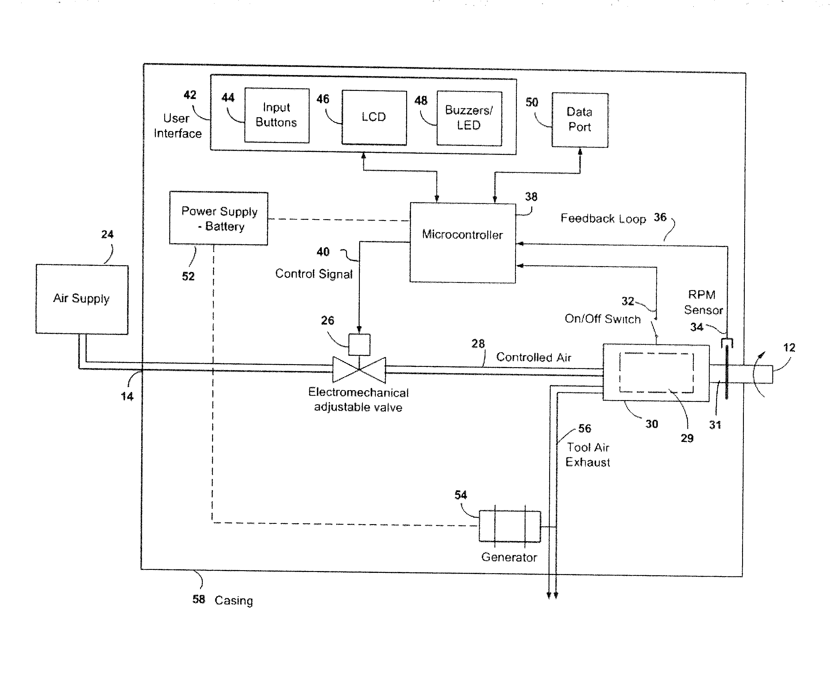
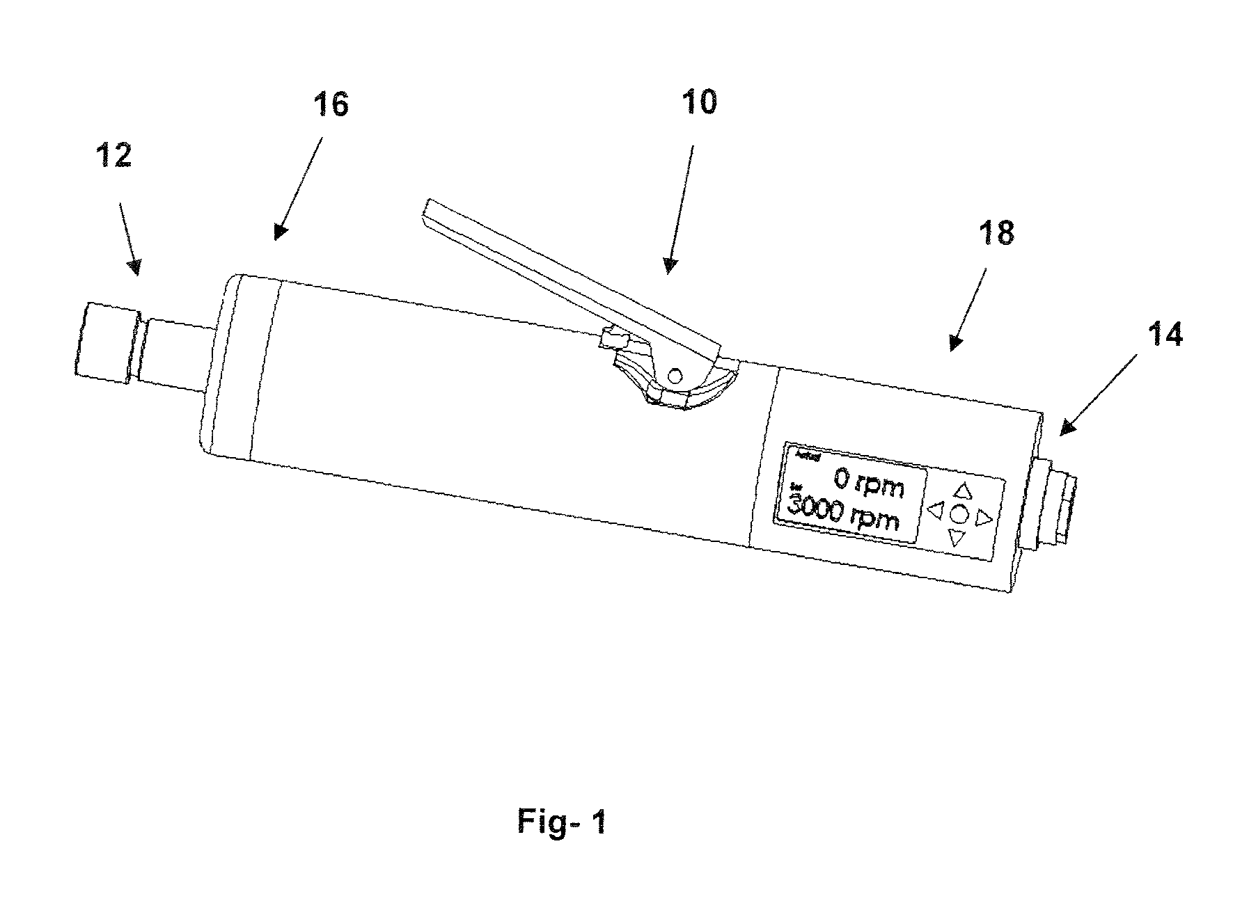
[0030]Referring to FIG. 1 in greater detail and by reference characters thereto, there is illustrated a pneumatic hand tool 10 with the incorporated speed control feature of the present invention. The rotary speed controller 18 can be connected to a conventional pneumatic rotary hand tool 10 that uses a rotary vane motor or to any other type of rotary pneumatic motor

[0031]It will be understood that the above hand tool 10 is of a type well known in the art and is for purposes of illustration only. The tool 10 has an arbour end 12 and an air inlet end coupling 14. In this preferred embodiment, the speed controller 18 is incorporated into the hand tool along with a speed sensor 16. This integrated approach maximizes the response time of the controller since it can adjust the air intake volume to any changes in rotary speed of the tool.

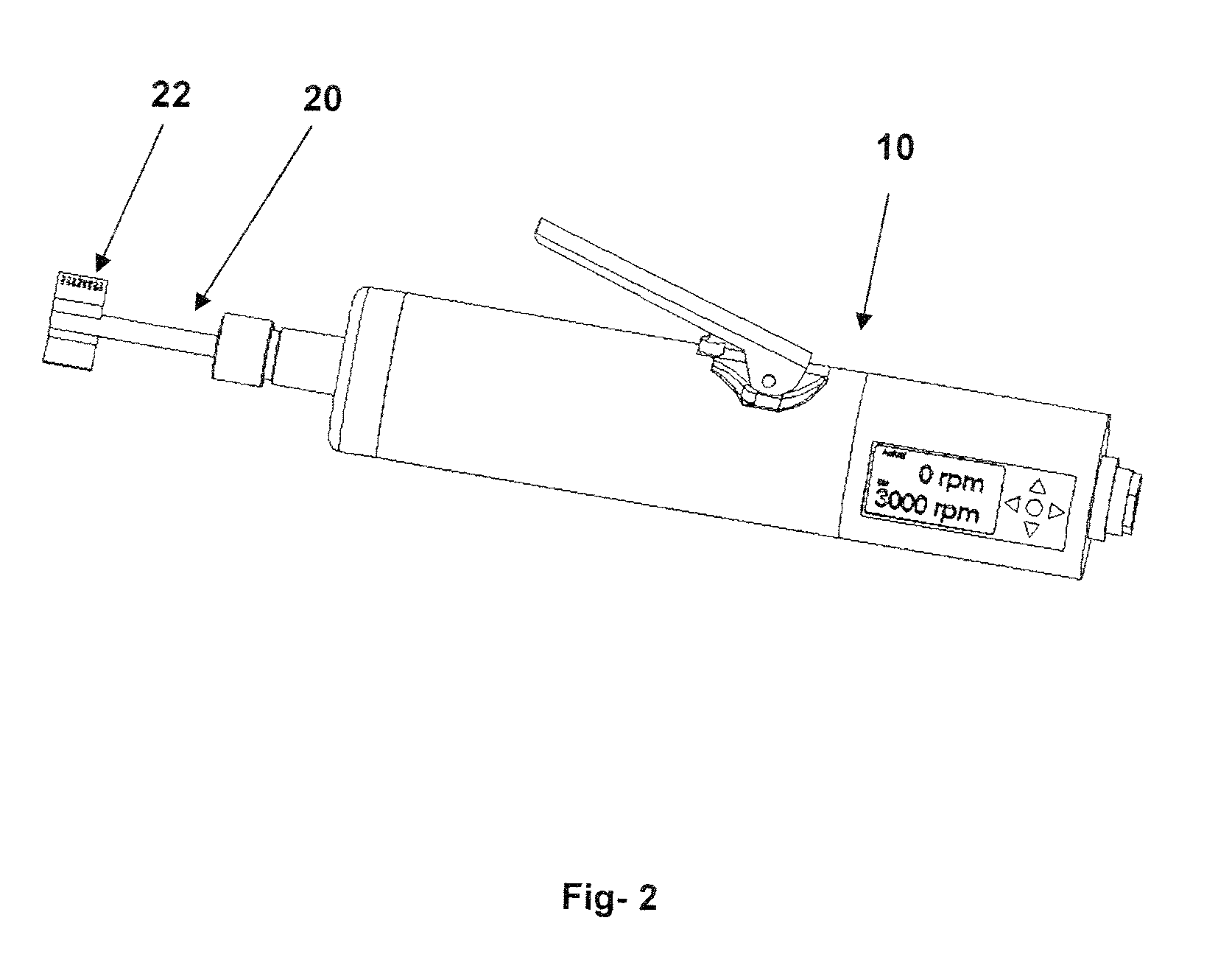
[0032]FIG. 2 illustrates the use of the pneumatic hand tool 10 with the integrated rotational speed controller of the present invention to perform flappe...


PUM


Abstract

The rotational speed of a pneumatic hand tool is adjusted in real time to maintain a selected speed level irrespective of exterior parameters affecting the performance of the tool. The apparatus is comprised of a rotational speed sensor installed directly on the tool, a digital microprocessor using control algorithms, and a valve to adjust the flow of air to the tool.

Description

CROSS-REFERENCE TO RELATED APPLICATION[0001]This application is a C-I-P of application Ser. No. 12 / 460,836, filed Jul. 24, 2009 and which claims priority based on U.S. Provisional Application Ser. No. 61 / 135,993 filed Jul. 25, 2008.TECHNICAL FIELD[0002]The present invention relates to a pneumatic hand tool rotational speed controller for controlling the operating rotational speed of a driven shaft of a pneumatic hand tool and its method of operation.BACKGROUND ART[0003]Pneumatic hand tools are portable tools powered by compressed air and are used to perform specific operations such as cutting, grinding, sanding, polishing, deburring, drilling, and peening.[0004]Pneumatic hand tools do not currently offer a method to display and control their rotational speed. They will therefore operate at their maximum speed if sufficient air is available. Since the attachment (ex: abrasive, drill bit, peening flap) used with the hand tool requires a specific speed for optimum performance, operator...

Claims


Application Information

Patent Timeline
IPC IPC(8): B25F5/00
CPCB24B23/026B25F5/001B24B49/00B24B39/006
Inventor FORGUES, SYLVAINLABELLE, BRIGITTE
Owner FORGUES SYLVAIN
Why Eureka
Try Eureka