Heat exchanger device

a heat exchanger and cyclic technology, applied in the direction of electrical equipment, thermoelectric devices with magnetic permeability thermal change, lighting and heating apparatus, etc., can solve the problem that the heat cycling characteristics of the above described cyclic heat exchanger are clearly unacceptable for a thermomagnetic generator

Inactive Publication Date: 2011-04-21
ABB RES LTD
View PDF5 Cites 5 Cited by
  • Summary
  • Abstract
  • Description
  • Claims
  • Application Information

AI Technical Summary

Benefits of technology

[0008]It is therefore an object of the present invention to provide a heat exchanger device, by which the above described drawbacks and limitations associated with the known device are eliminated or at least alleviated.
[0009]It is a particular object of the invention to provide such heat exchanger device, which can be used efficiently in a thermomagnetic generator system that converts thermal energy to electric energy.
[0017]The present invention features a cyclic heat exchanger device, which is simple, reliable, and robust, and by which temperature variations along the heat exchanger device can be essentially eliminated.

Problems solved by technology

The heat cycling characteristics of the above described cyclic heat exchanger is clearly unacceptable for a thermomagnetic generator.

Method used


Image

  • Heat exchanger device
  • Heat exchanger device
  • Heat exchanger device

Examples


Embodiment Construction

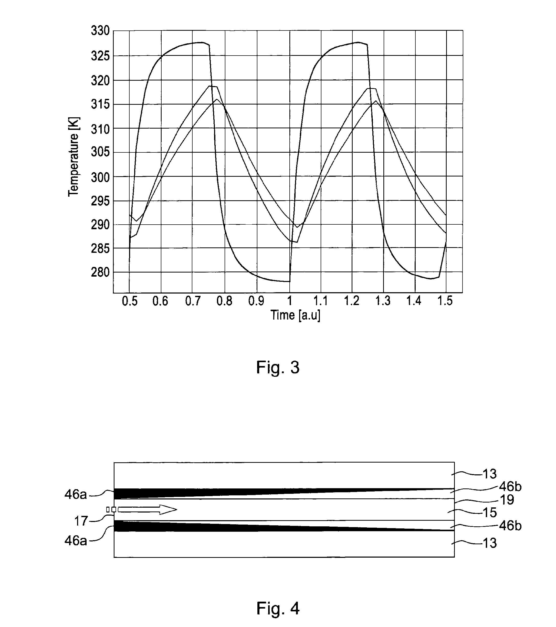
[0027]FIG. 4 displays a heat exchanger device according to an embodiment of the invention. The heat exchanger device comprises a body 13 and at least one channel 15 located in the body 13, through which a heat exchange fluid is adapted to be guided, thereby providing heat transfer between the heat exchange fluid and the material of the body 13. The body can have virtually any shape but is illustrated as being comprised of parallel plates.

[0028]The heat exchange fluid may be provided in the form of a pulse train, alternating between different temperatures at a given frequency. In such instance, the heat exchanger device is referred to as a cyclic heat exchanger device.

[0029]If such cyclic heat exchanger device is to be used in a generator system of an electric power plant for converting thermal energy to electric energy, the body 13 is made of or comprises a thermomagnetic material such as e.g. gadolinium.

[0030]The heat exchanger device comprises further surface layers 46a facing the...


PUM


Abstract

A heat exchanger device includes a body and at least one channel located in the body, through which a heat exchange fluid is adapted to be guided, thereby providing heat transfer per unit area between the heat exchange fluid and the material of the body, wherein the body has a material composition and / or dimensions such that the amount of heat transfer per unit area between the heat exchange fluid and the material of the body is essentially constant along the direction of the channel.

Description

CROSS-REFERENCE TO RELATED APPLICATIONS[0001]The present application is a continuation of pending International patent application PCT / EP2009 / 054973 filed on Apr. 24, 2009, which designates the United States and claims priority from European patent application 08155483.4 filed on Apr. 30, 2008, the content of which is incorporated herein by reference.FIELD OF THE INVENTION[0002]The present invention generally relates to heat exchanger devices. The invention is preferably, but not exclusively, intended for a generator system for converting thermal energy to electric energy.BACKGROUND OF THE INVENTION[0003]In known generator systems for converting thermal energy to electric energy there is provided a magnetic circuit of a suitable magnetic material and a coil arranged around the magnetic circuit. A temperature-varying arrangement varies the temperature of the magnetic circuit alternately above and below a phase transition temperature such as the Curie point of a magnetic material of t...

Claims


Application Information

Patent Timeline
Patent Type & Authority Applications(United States)
IPC IPC(8): H02N11/00F28D15/00
CPCF28F13/14F28F2255/00H01L37/04H10N15/20
Inventor RUSSBERG, GUNNAR
Owner ABB RES LTD
Why Eureka
Try Eureka