Electronic device

a technology of electronic devices and charging stations, applied in the direction of robotic cleaning machines, cleaning equipment, transportation and packaging, etc., can solve problems such as safety concerns, achieve the effects of enhancing the safety of the main unit and the charging station in use, avoiding accidents, and minimizing the probability of a user

Active Publication Date: 2011-04-21
MSI COMP SHENZHEN
View PDF10 Cites 62 Cited by
  • Summary
  • Abstract
  • Description
  • Claims
  • Application Information

AI Technical Summary

Benefits of technology

[0015]In the electronic device of the present invention, the first electrode and the second electrode of the charging station are disposed on different planes, so as to minimize the probability for a user to touch the first electrode and the second electrode at the same time by mistake, thereby avoiding the occurrence of accidents like electric shocks or strokes. Further, due to the characteristic that the first electrode and the second electrode of the charging station are disposed on different planes, when the main unit is connected to the charging s...

Problems solved by technology

Since the positive and negative conducting strips of the recharging terminal and the power terminal contact at the same time in the recharging operation, sparkles may be generated at the moment that the recharging terminal contacts the power terminal, thereby causing safety concer...

Method used


Image

  • Electronic device
  • Electronic device
  • Electronic device

Examples


first embodiment

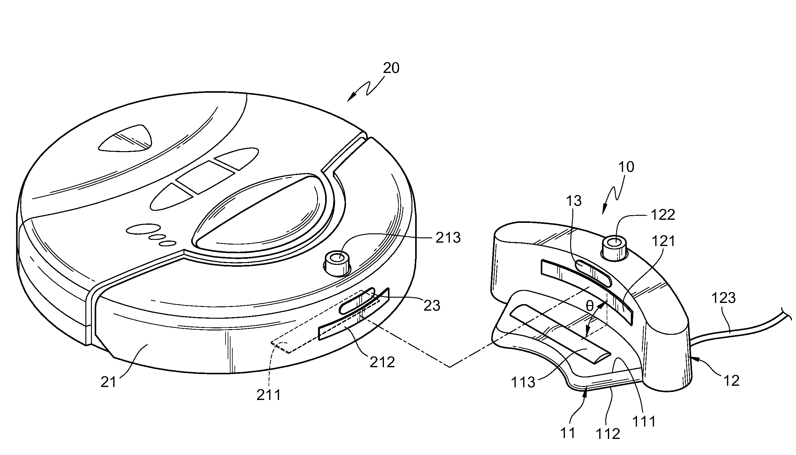
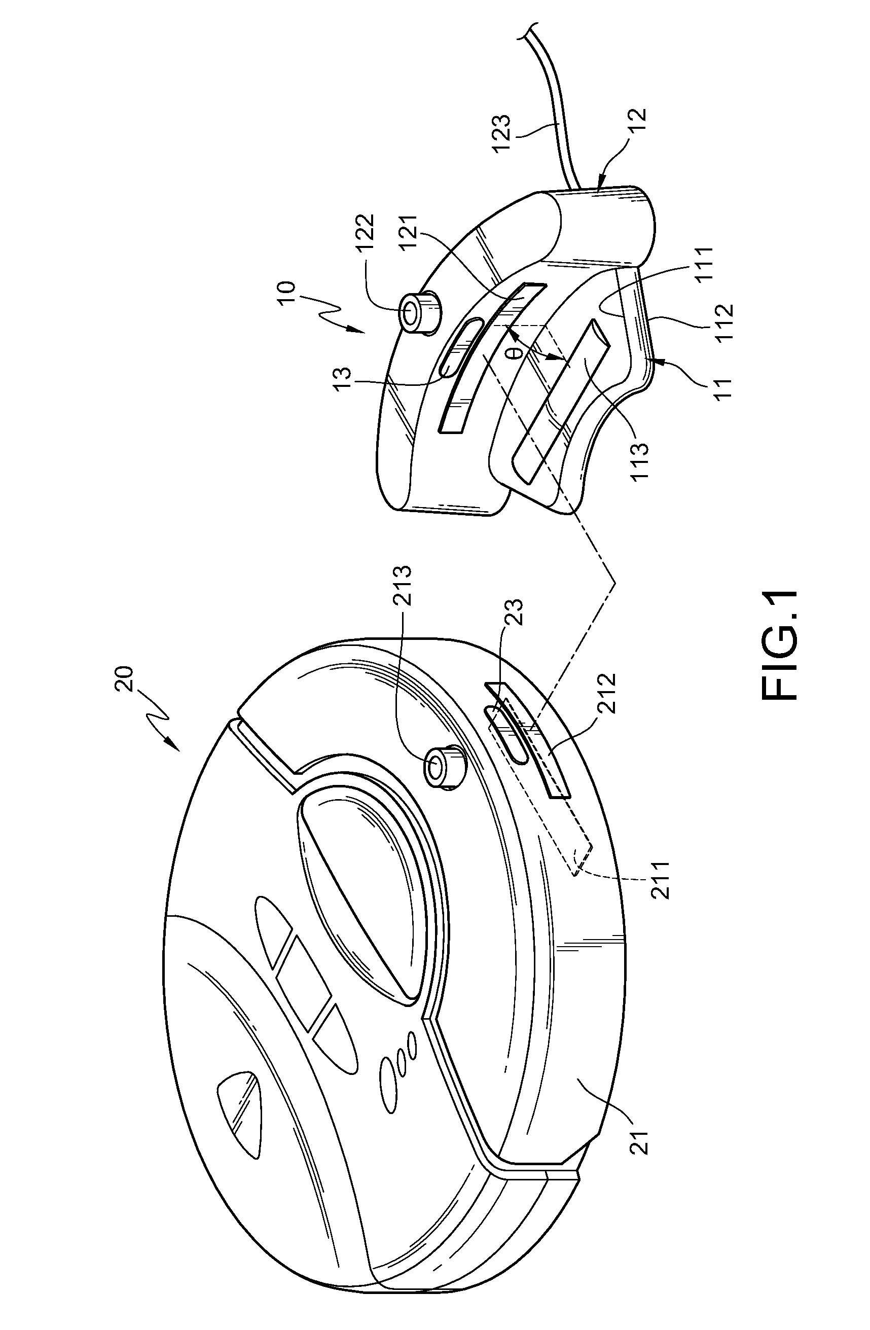
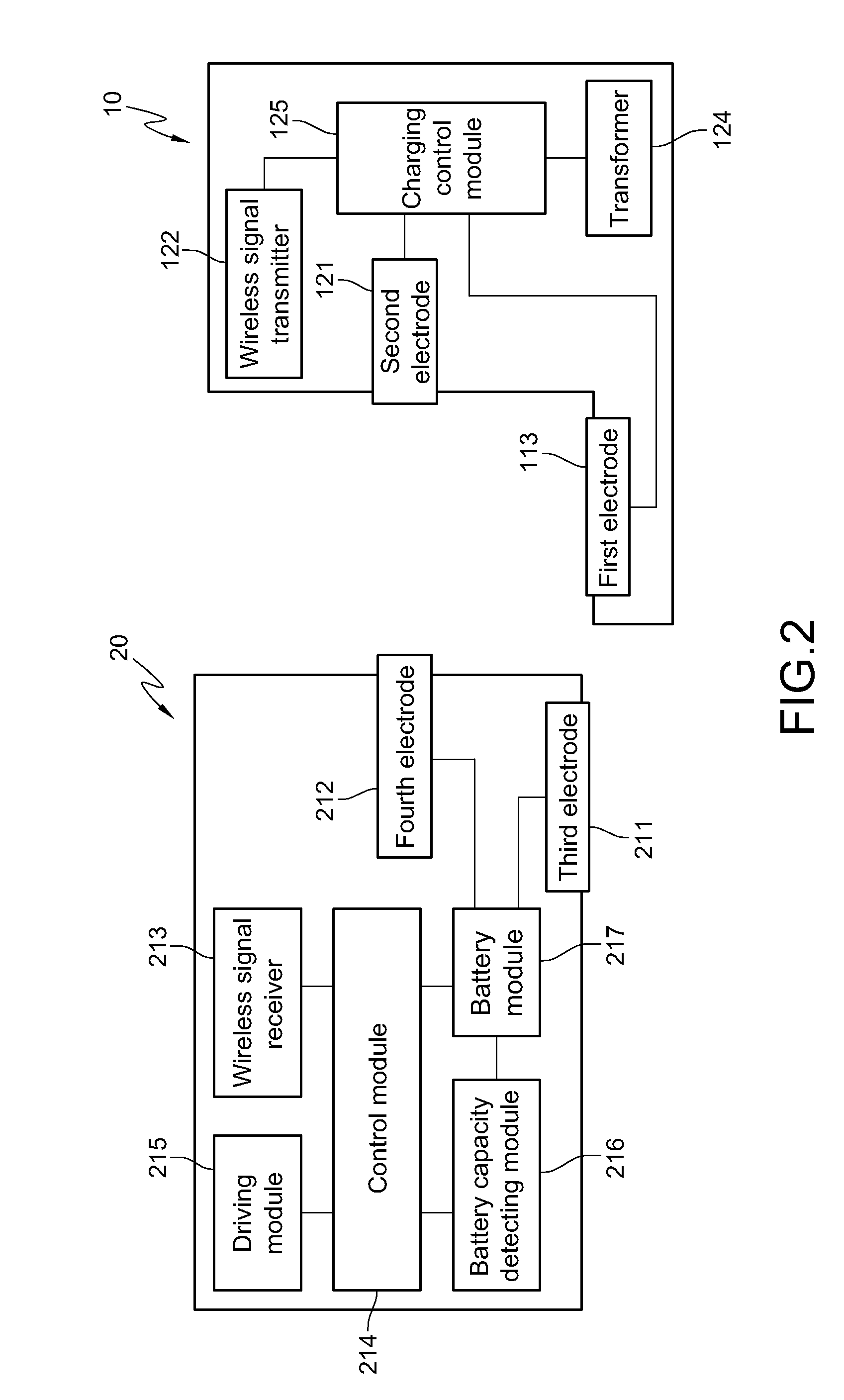
[0028]Referring to FIGS. 1 and 2, the electronic device in the present invention comprises a charging station 10 and a main unit 20. The charging station 10 has a carrier 11 and a seat 12. The carrier 11 has a surface 111 and a bottom surface 112 opposite thereto, and the bottom surface 112 of the carrier 11 is placed on a ground surface (not shown). A negative first electrode 113 is disposed on the surface 111 of the carrier 11. The seat 12 stands upright on the surface 111 of the carrier 11, and is spaced from the first electrode 113 by a distance. A positive second electrode 121 and a wireless signal transmitter 122 are disposed on a side surface of the seat 12 adjacent to the first electrode 113, and the wireless signal transmitter 122 is located above the second electrode 121. The first electrode 113 and the second electrode 121 may also be designed into a positive electrode and a negative electrode. In this embodiment, for ease of illustration, the first electrode 113 is a neg...

second embodiment

[0041]In the electronic device of the present invention, the charging station 10 further comprises a plurality of openings 114 and a conducting switch 15, and the first electrode 113 passes through each of the openings 114 with a plurality of cylindrical structures. The first electrode 113 has a contact portion 1131, a retaining portion 1132, and a conductive portion 1133. The retaining portion 1132 is annularly disposed between the contact portion 1131 and the conductive portion 1133, an outer diameter of the contact portion 1131 matches with an aperture of the openings, and an outer diameter of the retaining portion 1132 is larger than the aperture of the openings 114. Therefore, when the first electrode 113 passes through the openings 114 of the carrier 11, the contact portion 1131 of the first electrode 113 is exposed out of the surface 111 of the carrier 11, the retaining portion 1132 and the conductive portion 1133 are accommodated in the carrier 11, and the retaining portion ...


PUM


Abstract

An electronic device includes a charging station and a main unit. The charging station has a first electrode and a second electrode. The first electrode and the second electrode form an angle therebetween, and the main unit has a third electrode and a fourth electrode. When the main unit is connected to the charging station, the main unit firstly contacts the second electrode with the fourth electrode, and then contacts the first electrode with the third electrode, so as to be recharged by the charging station.

Description

CROSS-REFERENCE TO RELATED APPLICATIONS[0001]This non-provisional application claims priority under 35 U.S.C. §119(a) on Patent Application No(s). 098219192 filed in Taiwan, R.O.C. on Oct. 16, 2009, the entire contents of which are hereby incorporated by reference.BACKGROUND OF THE INVENTION[0002]1. Field of Invention[0003]The present invention relates to an electronic device, and more particularly to an electronic device having a charging station.[0004]2. Related Art[0005]With the rapid development of electronic industry, various types of electronic products have been widely applied in people's daily life. For some electronic products, by using a battery module (such as a rechargeable battery) configured therein, these products can be operated without an external power supply, thereby enhancing the convenience of utilizing the electronic products, for example, mobile phones, wireless phones, and intelligent home appliances such as robot cleaners.[0006]Although this type of electron...

Claims


Application Information

Patent Timeline
IPC IPC(8): H02J7/00
CPCA47L2201/022H02J7/0044
Inventor PAI, HSIN YI
Owner MSI COMP SHENZHEN
Why Eureka
Try Eureka