
Display device, display method and computer program

a display method and computer program technology, applied in the field of display devices, can solve problems such as crosstalk, and achieve the effect of reducing crosstalk and tailing phenomena, and appropriately performing overdriv

Inactive Publication Date: 2011-04-21
SONY CORP
View PDF4 Cites 26 Cited by
  • Summary
  • Abstract
  • Description
  • Claims
  • Application Information

AI Technical Summary

Benefits of technology

The patent text describes a problem with overdrive processing for 3D images in display devices. Due to the liquid crystal not settling into a steady state, crosstalk occurs when displaying 2D images and tailing occurs when displaying 3D images. The patent proposes a system and method to detect the gradation difference between frames and change the target value of the display output to suppress the occurrence of crosstalk and tailing.

Problems solved by technology

However, with this type of display device, crosstalk may occur due to characteristics of the display device and the shutter glasses, such as an insufficient liquid crystal response speed (when a liquid crystal panel is used as a screen) and insufficient contrast of the liquid crystal shutters of the shutter glasses.

Method used


Image

  • Display device, display method and computer program
  • Display device, display method and computer program
  • Display device, display method and computer program

Examples


Embodiment Construction

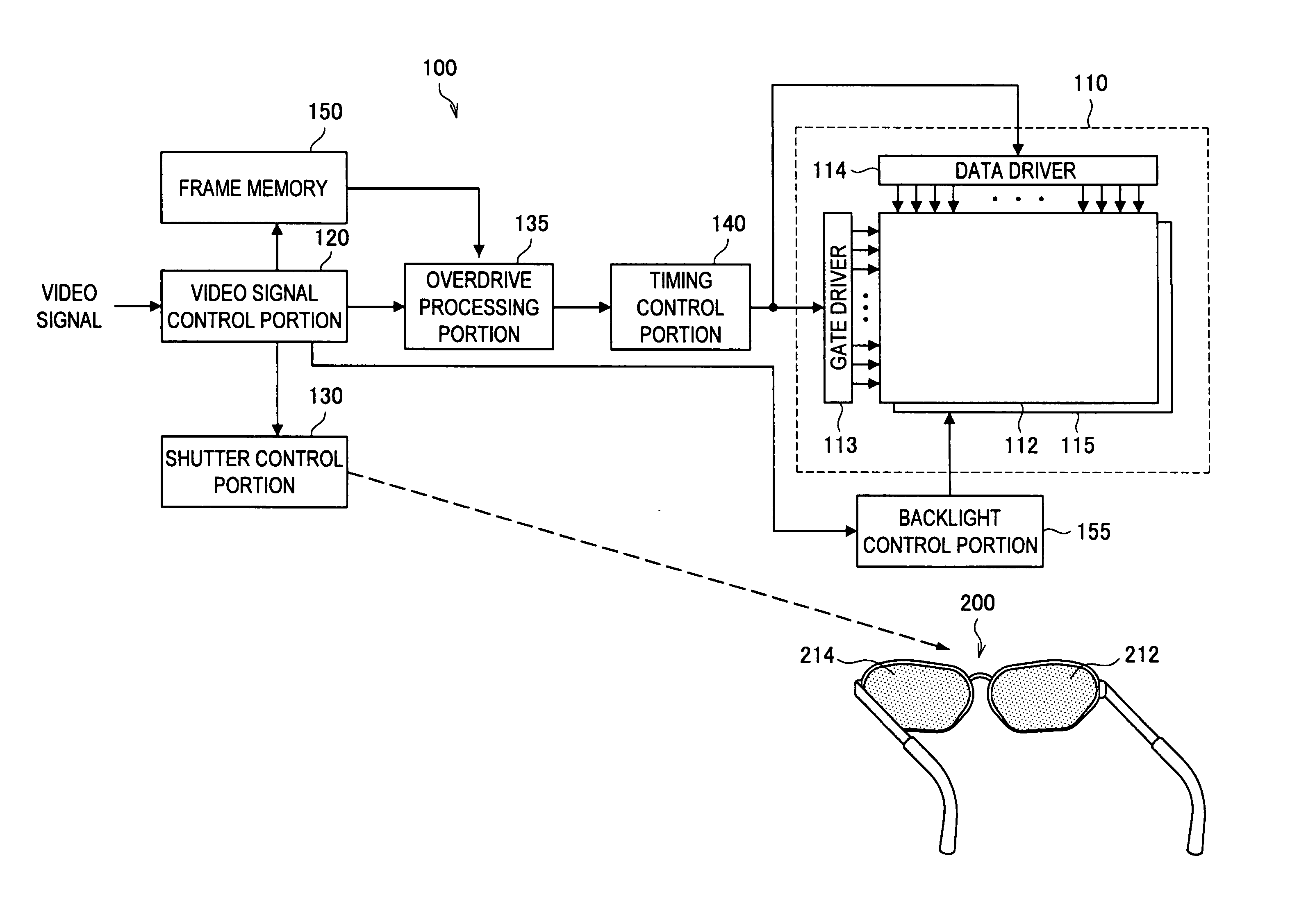
[0034]Hereinafter, preferred embodiments of the present invention will be described in detail with reference to the appended drawings. Note that, in this specification and the appended drawings, structural elements that have substantially the same function and structure are denoted with the same reference numerals, and repeated explanation of these structural elements is omitted.

[0035]Explanation will be made in the following order.

[0036]1. An embodiment of the present invention[0037]1-1. Configuration of display device according to an embodiment of the present invention[0038]1-2. Functional configuration of display device according to the embodiment of the present invention[0039]1-3. Operation of display device according to the embodiment of the present invention

[0040]2. Conclusion

1. AN EMBODIMENT OF THE PRESENT INVENTION

1-1. Configuration of Display Device According to an Embodiment of the Present Invention

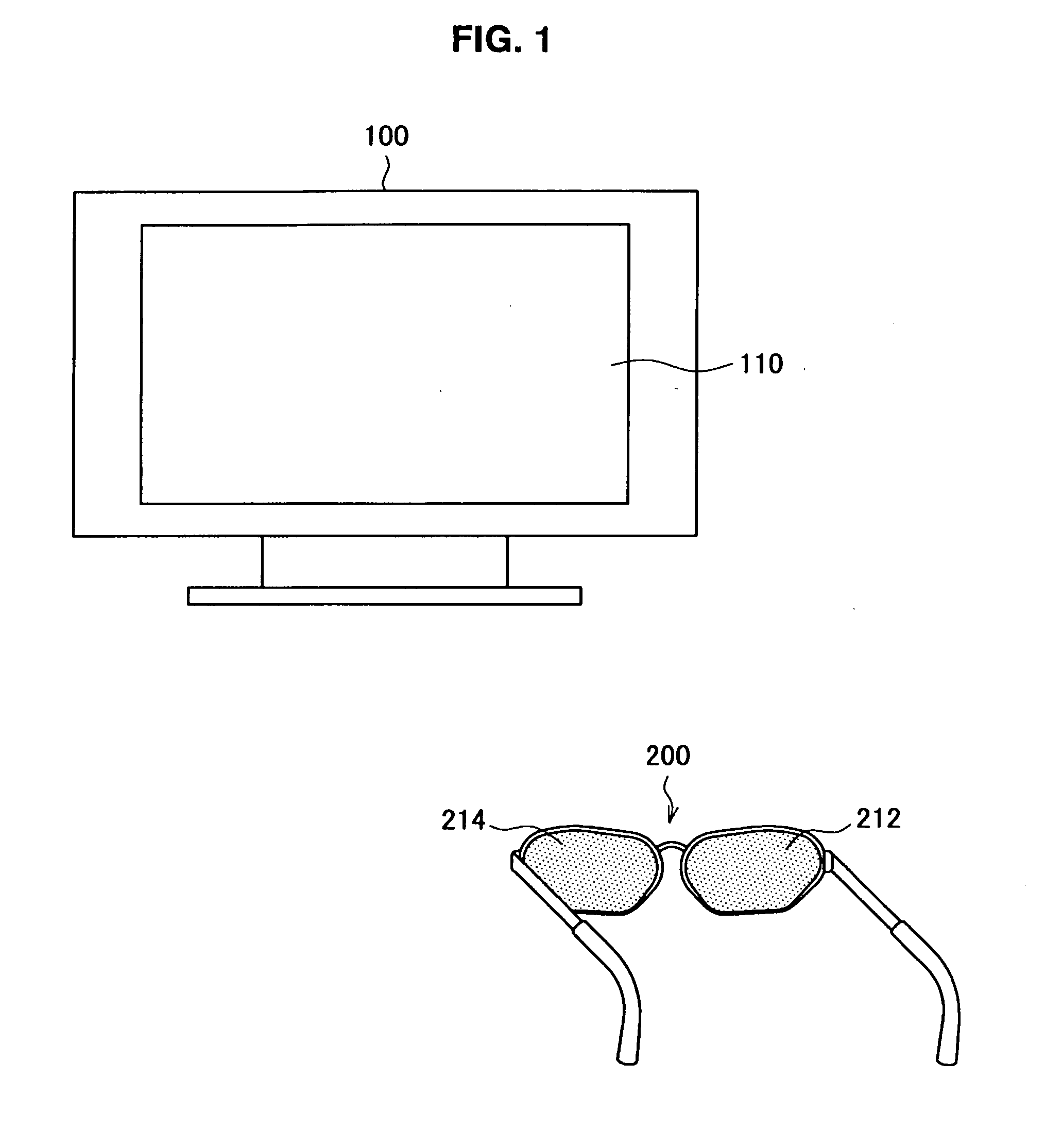
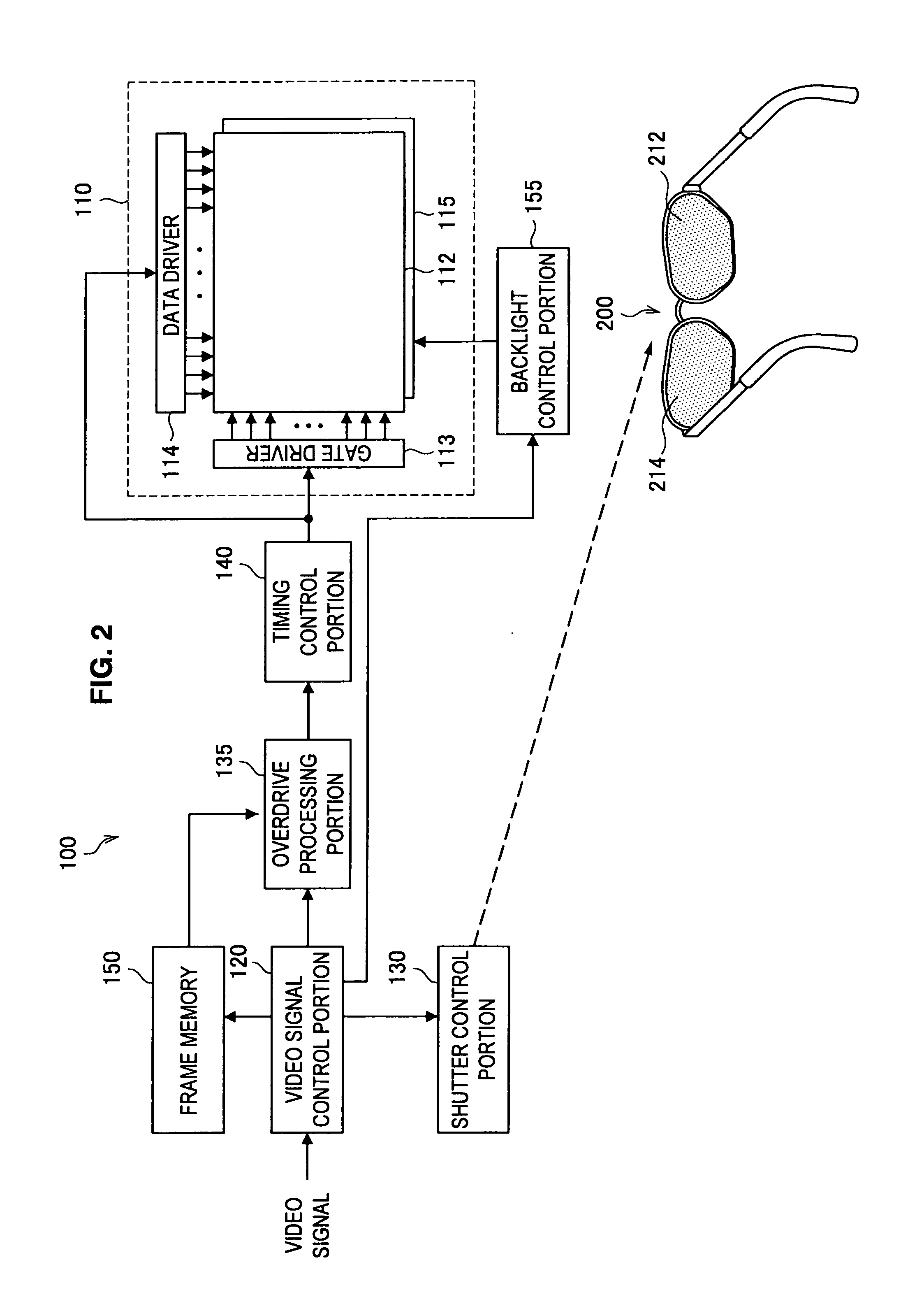
[0041]Hereinafter, a configuration of a display device 100 according to an ...


PUM


Abstract

A display system and display method in which a gradation difference between a first frame and a second frame of a video signal is detected, a determination is made as to whether the gradation difference is of a first state or a second state, and a target value of an output of a display is changed based on the result of the determination.

Description

CROSS-REFERENCE TO RELATED APPLICATION[0001]The present application claims priority from Japanese Patent Application No. JP 2009-242079 filed in the Japanese Patent Office on Oct. 21, 2009, the entire content of which is hereby incorporated herein by reference.BACKGROUND OF THE INVENTION[0002]1. Field of the Invention[0003]The present invention relates to a display device, a display method and a computer program.[0004]2. Description of the Related Art[0005]Display devices exist in which an image displayed on a screen is perceived by a viewer as a stereoscopic image. A time division display scheme is known as a technique to cause the viewer to perceive an image displayed on this type of display device as a stereoscopic image. In the time division display scheme, an image for the left eye and an image for the right eye are alternately displayed on the entire screen at very short intervals (See Japanese Patent Application Publication No. JP-A-1997-138384, Japanese Patent Application Pu...

Claims


Application Information

Patent Timeline
Patent Type & Authority Applications(United States)
IPC IPC(8): H04N13/04
CPCG02B27/2264G09G3/003G09G3/3648H04N13/0497G09G2340/16H04N13/0007H04N13/0438G09G2320/0285H04N13/341H04N13/106H04N13/398G02B30/24
Inventor NAKAGAWA, MAKOTONAKAHATA, YUJISUZUKI, TOSHIAKI
Owner SONY CORP
Learn More