Light pen

a light pen and pen body technology, applied in the field of light pen, can solve the problems of relatively large elastic fatigue problem, and the inability to use the spring as a switch structure, and achieve the effect of shortening the strok

Active Publication Date: 2011-04-21
K LASER TECH
View PDF6 Cites 5 Cited by
  • Summary
  • Abstract
  • Description
  • Claims
  • Application Information

AI Technical Summary

Benefits of technology

[0007]The main object of the present invention is to provide a light pen, replacing a spring with two magnets to allow a switch structure of the light pen to be more durable and dependable.
[0008]Another object of the present invention is to provide a light pen, capable of being used as a switch structure for a shorter stroke between two electric contact points from a separation state to a contact state.
[0014]wherein, the pen shell is used for accepting a battery, two adjacent sides of the first and the second magnets are respectively provided with different magnetism; the first and the second magnets are always separated and approach each other only if an external force is acted on them. The first pin and the second pin of the luminescence element are ordinarily respectively do not turn on a circuit constituted by a first terminal and a second terminal of the battery to allow the luminescence element not to radiate; when the first and the second magnets are near, the first pin and the second pin of the luminescence element respectively turn on the circuit constituted by the first terminal and the second terminal of the battery to allow the luminescence element to radiate; whereby, the switch structure of the light pen is enabled not to yield elastic fatigue and have a shorter stroke.

Problems solved by technology

A spring in the movable luminescence device is used for providing switching elasticity; this might yield elastic fatigue problem relatively.
Besides, because the spring with longer deformation can then have a larger spring force, when a distance between two electric contact points is too small and a stroke between the both from a separation state to a contact state is too short, the spring can then not be used as a switch structure.

Method used


Image

  • Light pen
  • Light pen
  • Light pen

Examples


Embodiment Construction

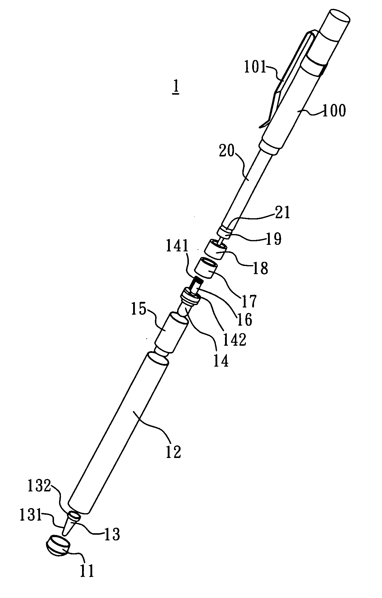
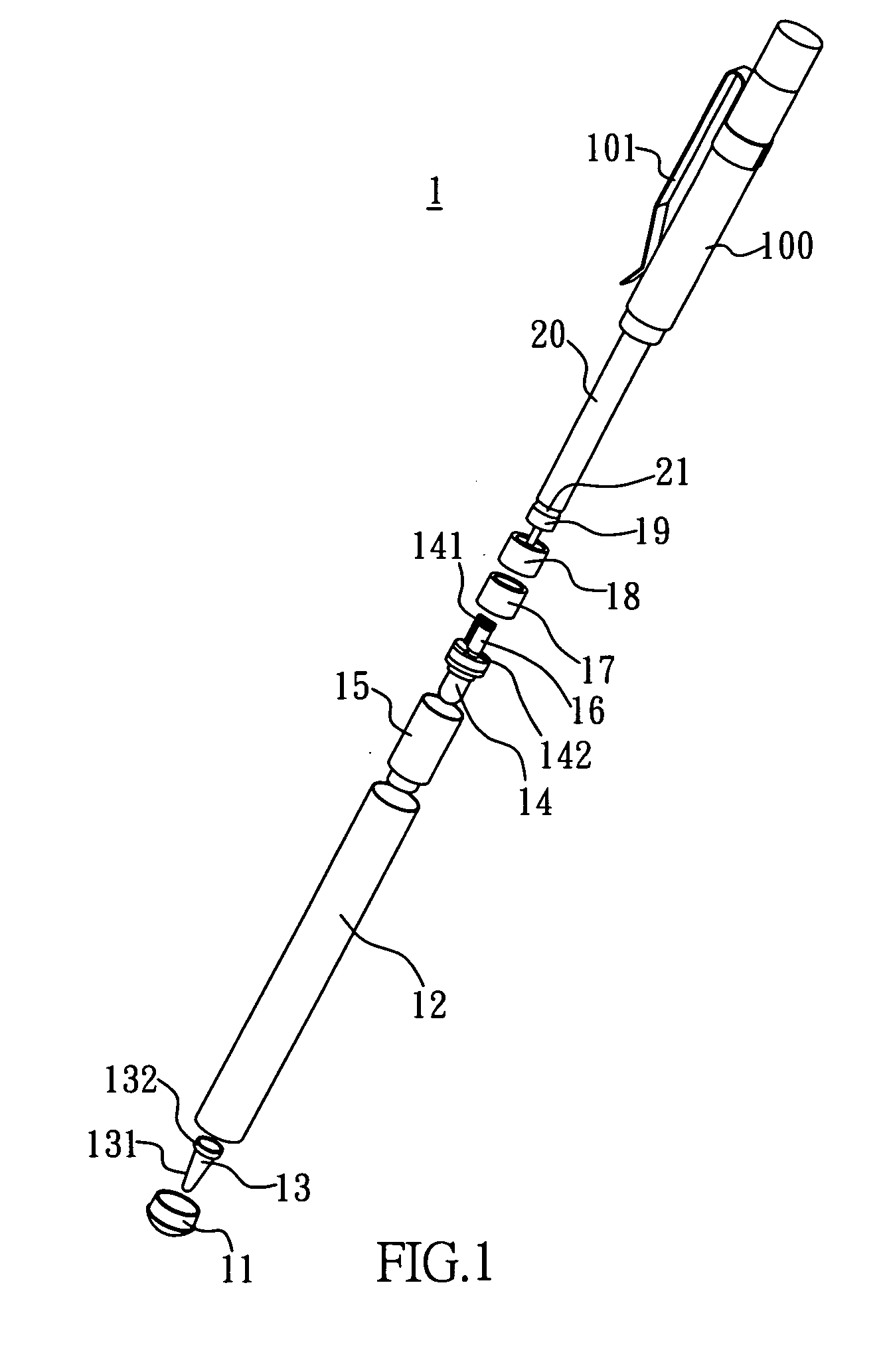
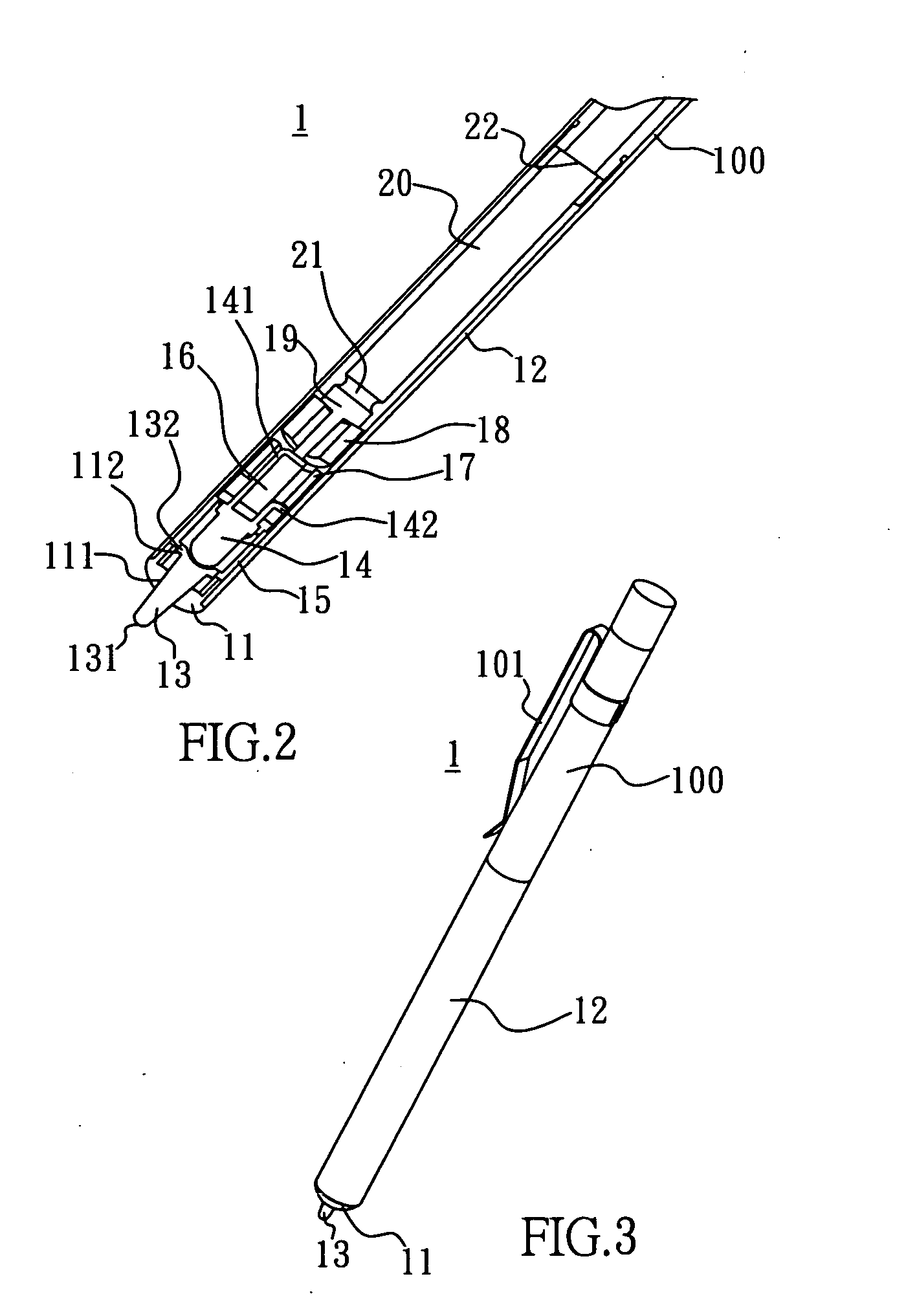
[0019]Please refer to FIGS. 1, 2 and 3. A light pen 1 of the present invention is adapted to allow a switch structure to be more durable and dependable and have a shorter stroke, comprises a lower shell 11, a middle shell 12, a light guiding bar 13, a luminescence element, a lower cover 15, an insulation isolator 16, a first magnet 17, a second magnet 18, a conducting pin 19, a battery 20 and a upper shell 100: the lower shell 11 is tubular and a lower channel 111 of an inner part thereof is narrower than a upper channel 112 thereof;

[0020]the middle shell 12 is tubular and a lower end thereof is combined with the lower shell 11;

[0021]the light guiding bar 13 is used for guiding light, engaged in the lower shell 11; a front end 131 thereof is extended out of the lower shell 11, and a rear end thereof 132 is thicker and is lodged in the upper channel 112 of the lower shell 11;

[0022]the luminescence element, such as photodiode 14, has a first pin 141 and a second pin 142 in which the f...


PUM


Abstract

First and second magnets of a light pen according to the present invention are used for replacing a conventional spring to be a switch structure of the light pen. Whereby, the elastic fatigue problem is not yielded, the switch structure is enabled to be more durable and dependable and can be used as a switch structure for a light pen whose stroke between two electric contact points from a separation state to a contact state is shorter.

Description

BACKGROUND OF THE INVENTION[0001]1. Field of the Invention[0002]The present invention relates to a light pen, and more particularly to a light pen adapted to provide an input device for processing an input operation on an operation surface[0003]2. Description of Related Art[0004]Taiwan Patent No. 479190 entitled as “Data Input Device” discloses a movable luminescence device, which can be operated and moved by a user and emit at least two color lights; and a camera connected to a computer, which can capture and shoot light emitted from the movable luminescence device, and judge the color of the light and process and transfer the captured moving track of the light points of the movable luminescence device to a XY coordinate data so as to allow the computer device to process the index inputting function; the movable luminescence device is manufactured to be a pen shape, the photodiode is installed on a pen nib portion.[0005]A spring in the movable luminescence device is used for provid...

Claims


Application Information

Patent Timeline
Patent Type & Authority Applications(United States)
IPC IPC(8): F21V9/16
CPCB43K29/10
Inventor LIN, CHIH-HSIUNG
Owner K LASER TECH
Why Eureka
Try Eureka