Opposed tilting blade, vertical axis wind turbine power generator

a technology of vertical axis wind turbines and power generators, which is applied in the direction of rotors, greenhouse gas reduction, vessel construction, etc., can solve the problems of reducing the efficiency of the blades and generally lacking the efficiency of the horizontal axis wind turbines, so as to reduce the mechanical complexity

Active Publication Date: 2011-04-21
DEELEY PETER G R
View PDF24 Cites 16 Cited by
  • Summary
  • Abstract
  • Description
  • Claims
  • Application Information

AI Technical Summary

Benefits of technology

[0014]It is an object of the opposed tilting blade turbine for the vertical axis, wind driven turbine uses blades that rotate on the horizontal axis. The vertical axis elim...

Problems solved by technology

Many such windmills have been produced but the vertical axis wind turbines generally lack the efficiency of a traditional horizontal axis wind turbine.
In operation...

Method used


Image

  • Opposed tilting blade, vertical axis wind turbine power generator
  • Opposed tilting blade, vertical axis wind turbine power generator
  • Opposed tilting blade, vertical axis wind turbine power generator

Examples


Embodiment Construction

Drawings

Reference Numerals

[0033]

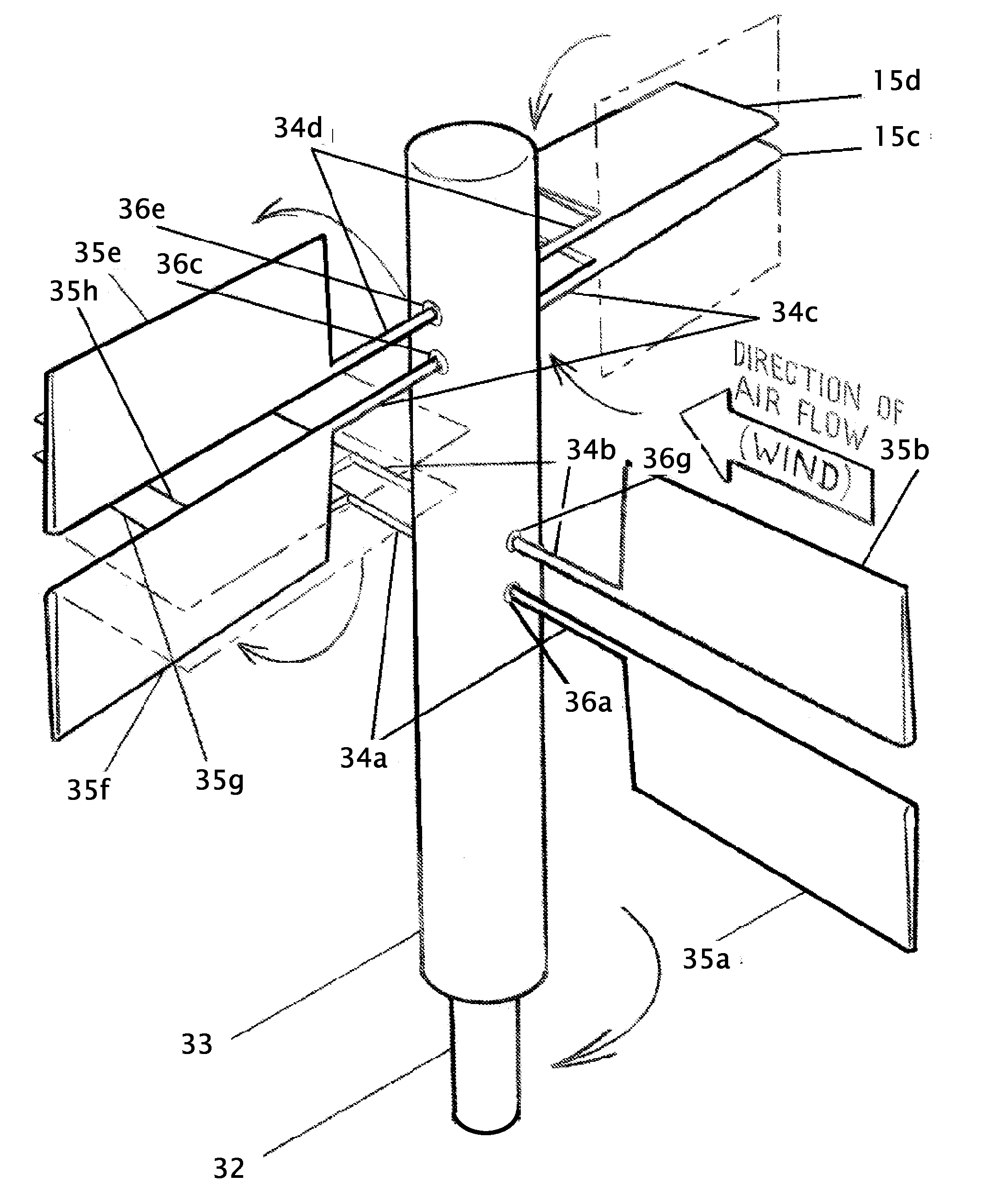
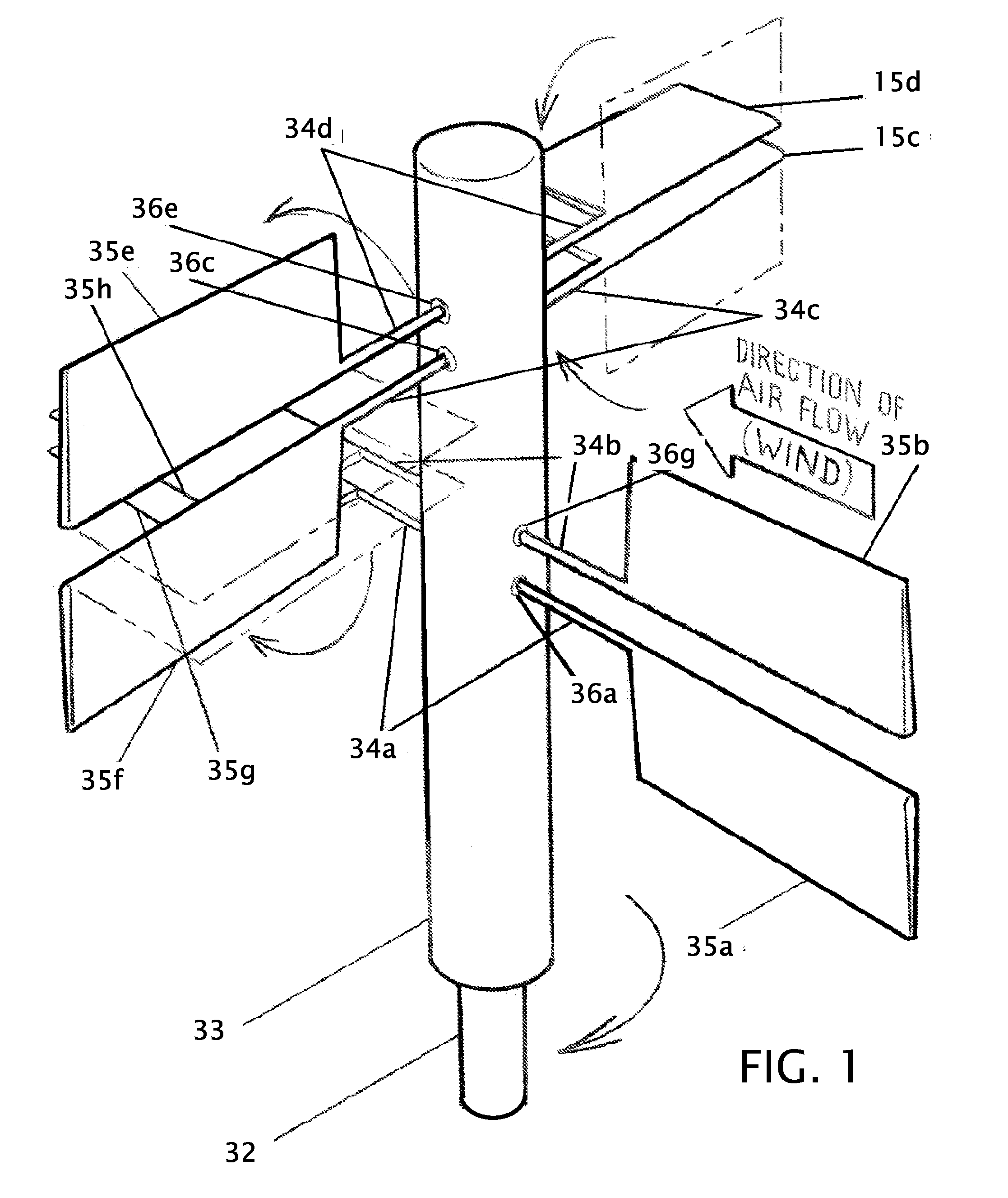
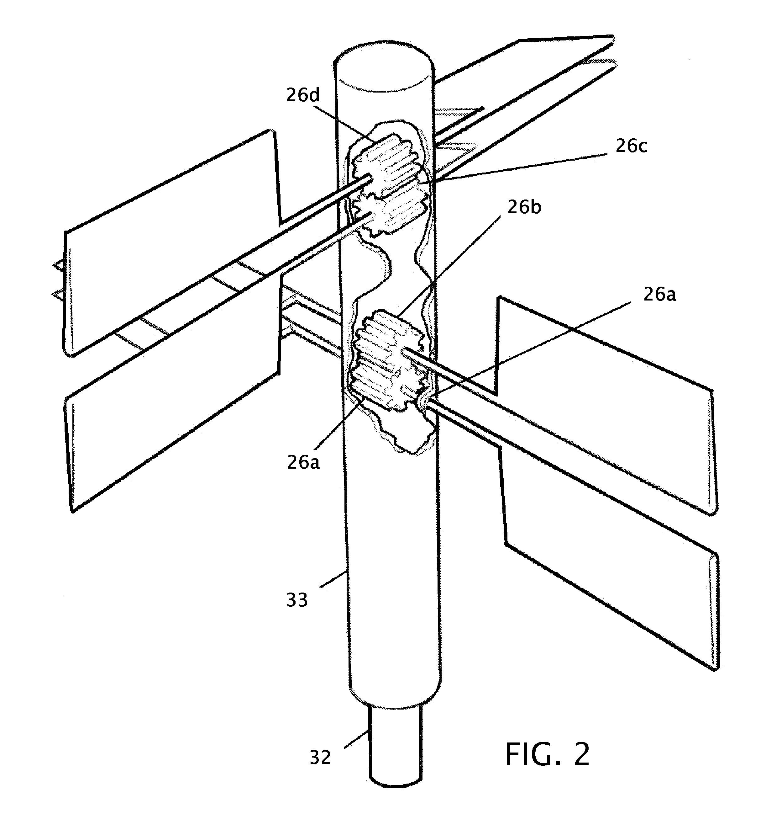
26a, 26b, 26c, 26d-26pgears27b, 27c, & 27dlevers28a, 28bRotational stabilizer29a, 29b, 29c, & 29dcounterweights30a, 30b, 30c & 30doverride motion stops31a, 31b, 31c & 31dstop levers32drive shaft33housing34a, 34b, 34c, 34d, 34e & 34f-34iblade shafts35a, 35b, 35c, 35d, 35e, 35f, 35g & 35hblades36a, 36c, 36e, 36g & 36h-36ibearings37a, 37b“S” belts38a, 38bbearing housings46a, 46b, 46c, 46e, 46f, 46g, & 46iroller or pulley47a, 47b, to 47o.belt, chain, cable or link48a to 48l.transfer bar49plate52a-52dcrank arm or lever arm53arod54a-54hBezel, crown or 45° gear55a-55b.Drive shaft

[0034]FIG. 1 shows a perspective of the opposed rotating blade, vertical axis wind turbine power generator, in accordance with the windmill and its blades assemblies including the blade shafts 34a, 34b, 34c, 34d, and the blades 35a, 35b, 35c, 35d, 35e, 35f, 35g, mounted to the housing 33. Each of the blades 35a, 35b, 35c, 35d, 35e, 35f, and 35g is wind foil shaped to minimize wind dr...


PUM


Abstract

Improvements in A wind generator, that may also be called and relates to, windmill, turbine or aero generator, on a vertical axis. The vertical axis gives the windmill the ability to be turned by air, or liquid if inverted, from any direction parallel to the earth's surface. Multiple blades rotate through a horizontal axis into the wind to lessen air resistance on one side while turning vertically on the other side to gain energy from the wind. The system is counter-weighted as needed, to reduce energy loss, by different methods including but not limited to gears, levers, pneumatics, cables, hydraulics or added counter-weight. The electrical generating machinery is below the blades or at the bottom of the vertical drive shaft.

Description

CROSS REFERENCE TO RELATED APPLICATION[0001]This application claims the benefit of Provisional 61 / 207,789 filed Feb. 18, 2009 the entire contents of which is hereby expressly incorporated by reference herein.STATEMENT REGARDING FEDERALLY SPONSORED RESEARCH OR DEVELOPMENT[0002]Not ApplicableTHE NAMES OF THE PARTIES TO A JOINT RESEARCH AGREEMENT[0003]Not ApplicableINCORPORATION-BY-REFERENCE OF MATERIAL SUBMITTED ON A COMPACT DISC[0004]Not ApplicableBACKGROUND OF THE INVENTION[0005]1. Field of the Invention[0006]This invention relates to improvements in a windmill. More particularly, the present windmill uses opposed tilting blades mounted on a vertical axis to generate power.[0007]2. Description of Related Art including information disclosed under 37 CFR 1.97 and 1.98[0008]This windmill harnesses the power of the wind and turns it into electricity via a generator. Many such windmills have been produced but the vertical axis wind turbines generally lack the efficiency of a traditional ...

Claims


Application Information

Patent Timeline
IPC IPC(8): B64C27/54
CPCY02E10/74F03D3/068
Inventor DEELEY, PETER G. R.
Owner DEELEY PETER G R
Why Eureka
Try Eureka