
Turbines And Turbine Blade Winglets

a technology of turbine blades and winglets, which is applied in the direction of liquid fuel engines, vessel construction, marine propulsion, etc., can solve problems such as blade degradation

Active Publication Date: 2011-04-21
GENERAL ELECTRIC CO
View PDF12 Cites 24 Cited by
  • Summary
  • Abstract
  • Description
  • Claims
  • Application Information

AI Technical Summary

Benefits of technology

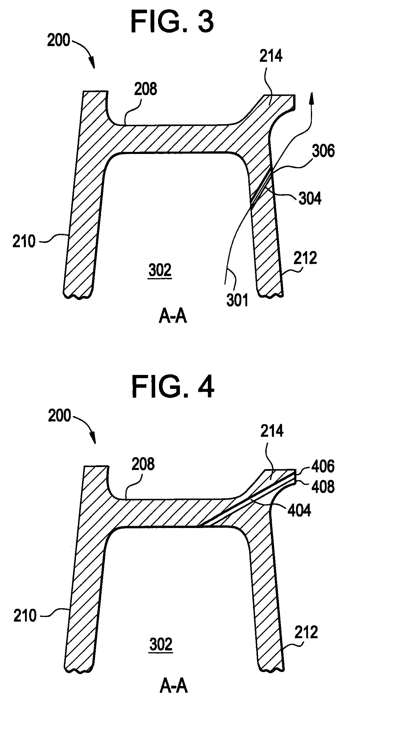
[0009]FIG. 3 illustrates a front cut-away view of an exemplary embodiment of the turbine blade along the line A-A of FIG. 2;
[0010]FIG. 4 illustrates a front cut-away view of another exemplary embodiment of the turbine blade along the line A-A of FIG. 2;
[0011]FIG. 5 illustrates a front cut-away view of an

Problems solved by technology

Turbine blades are subjected to high temperatures that cause degradation of the blades during engine operation.

Method used


Image

  • Turbines And Turbine Blade Winglets
  • Turbines And Turbine Blade Winglets
  • Turbines And Turbine Blade Winglets

Examples


Embodiment Construction

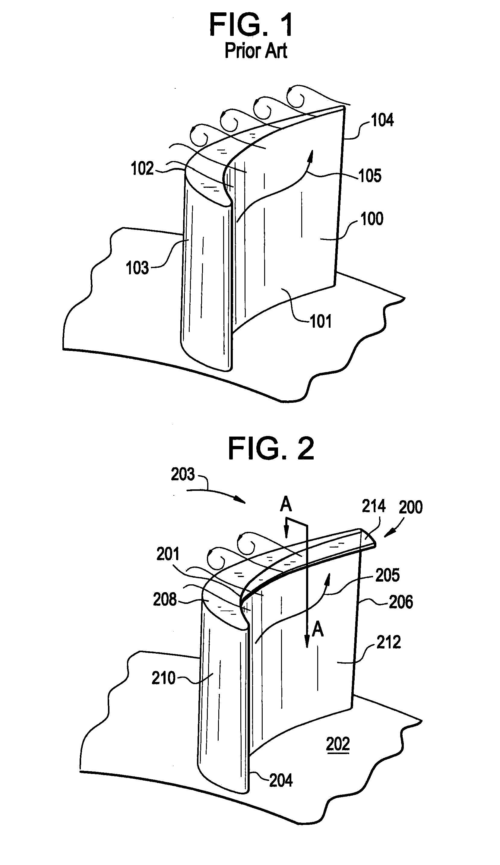
[0015]FIG. 1 illustrates a prior art example of a turbine blade 100. In operation, as the turbine blade 100 rotates, air flows from a pressure region 101 to a suction region 103 of the blade 100. The path of the air flow near a tip 102 of the blade is indicated by the arrow 105. The as the airflow approaches a trailing edge 104 of the blade, the airflow “leaks” over the tip 102. The amount of airflow that leaks over the tip 102 increases as the airflow approaches the trailing edge 104. The leakage of airflow over the tip 102 undesirably decreases the efficiency of the turbine blade, and increases the temperature of the tip 102. The increased temperature of the tip 102 region results in oxidation and wear of the tip 102 region material.

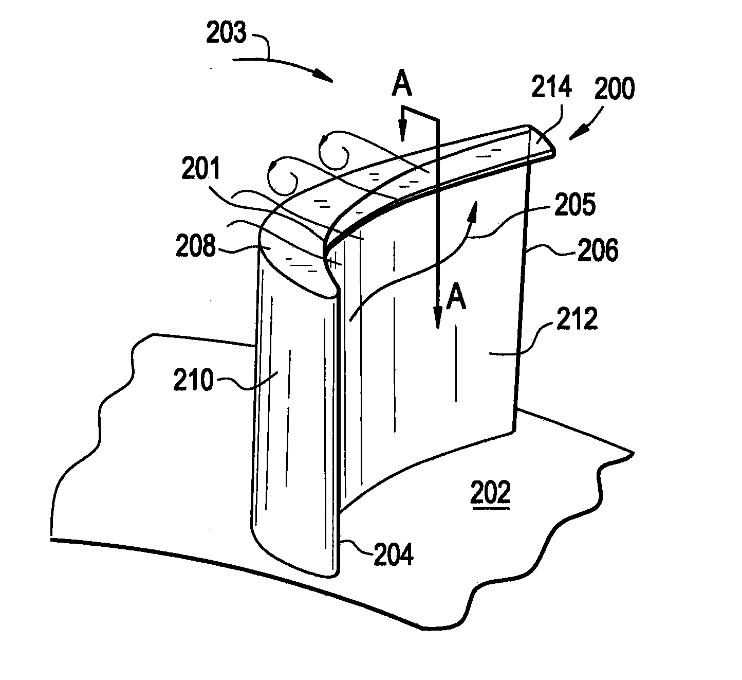
[0016]FIG. 2 illustrates an exemplary embodiment of a turbine blade 200 connected to a portion of a moveable rotor 202 of a turbine. The turbine blade (blade) 200 has an airfoil shaped body with a leading edge 204, a trailing edge 206, a distal blade t...


PUM


Abstract

A turbine blade includes a body having a leading edge, a trailing edge, a pressure side, a suction side, and a tip region, and a winglet arranged on the pressure side of the body in the tip region extending from a point in the tip region down stream of the leading edge to the trailing edge.

Description

BACKGROUND OF THE INVENTION[0001]The subject matter disclosed herein relates to turbine engines and particularly to turbine blades.[0002]Turbine blades are typically mounted on a rotor connected to a shaft that rotates in the turbine engine. Turbine blades are subjected to high temperatures that cause degradation of the blades during engine operation.BRIEF DESCRIPTION OF THE INVENTION[0003]According to one aspect of the invention, a turbine blade includes a body having a leading edge, a trailing edge, a pressure side, a suction side, and a tip region, and a winglet arranged on the pressure side of the body in the tip region extending from a point in the tip region down stream of the leading edge to the trailing edge.[0004]According to another aspect of the invention, a turbine engine includes a rotor assembly, and a plurality of turbine blades arranged on the rotor assembly at least one blade having a leading edge, a trailing edge, a pressure side, a suction side, a tip region, and ...

Claims


Application Information

Patent Timeline
IPC IPC(8): F01D5/14
CPCF01D5/20F01D5/145
Inventor WILLETT, JR., FRED THOMAS
Owner GENERAL ELECTRIC CO
Learn More