Rotational alignment of fluid delivery device

a fluid delivery and rotational alignment technology, applied in the field of rotational alignment of fluid delivery devices, can solve the problems of not knowing in which direction fluid flows, harming those regions, and risking the fluid moving in an undesired direction

Active Publication Date: 2011-04-21
JOHNSON & JOHNSON SURGICAL VISION INC
View PDF23 Cites 18 Cited by
  • Summary
  • Abstract
  • Description
  • Claims
  • Application Information

AI Technical Summary

Problems solved by technology

One issue with handpieces employing needles and sleeves is the proper orientation of the devices.
When a surgeon uses a handpiece fitted with a sleeve, he frequently employs the sleeve and needle in a region of the eye wherein he cannot see the orientation of the sleeve and / or the two fluid openings or ports provided and thus does not know in which direction fluid flows during the surgical procedure.
A surgeon typically views the procedure through a device such as a microscope, and her inability to see the orientation of the ports during the surgery can potentially raise at least two issues.
First, fluid flow toward certain parts of the eye chamber, such as the retina or cornea, can potentially harm those regions, while fluid flow toward other parts of the eye chamber can be essentially benign and permissible to properly perform the surgery.
Such surgeons employ fluid flow and ultrasonic power in tandem, and if the surgeon does not know the orientation of fluid flow he runs the risk of moving the fluid in an undesired direction, for example pushing away material he wishes to work on and break up.
Such an occurrence could potentially extend the duration of the surgery, and is undesirable.
Again, these ports may become obscured and the vitrectomy surgeon may be unable to establish the orientation of the ports when obscured or partially obscured.
In this instance, the needle can aspirate fluid from the eye through an opening, but again obscuration of the tip can be an issue.

Method used


Image

  • Rotational alignment of fluid delivery device
  • Rotational alignment of fluid delivery device
  • Rotational alignment of fluid delivery device

Examples


Embodiment Construction

[0027]The following description and the drawings illustrate specific embodiments sufficient to enable those skilled in the art to practice the system and method described. Other embodiments may incorporate structural, logical, process and other changes. Examples merely typify possible variations. Individual components and functions are generally optional unless explicitly required, and the sequence of operations may vary. Portions and features of some embodiments may be included in or substituted for those of others.

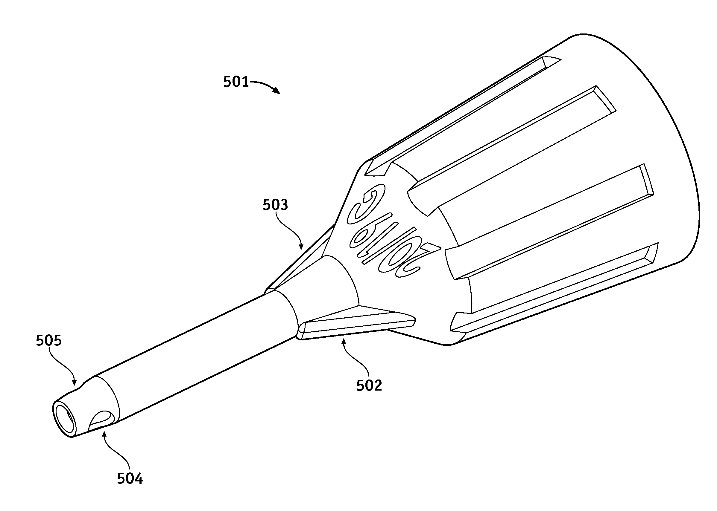
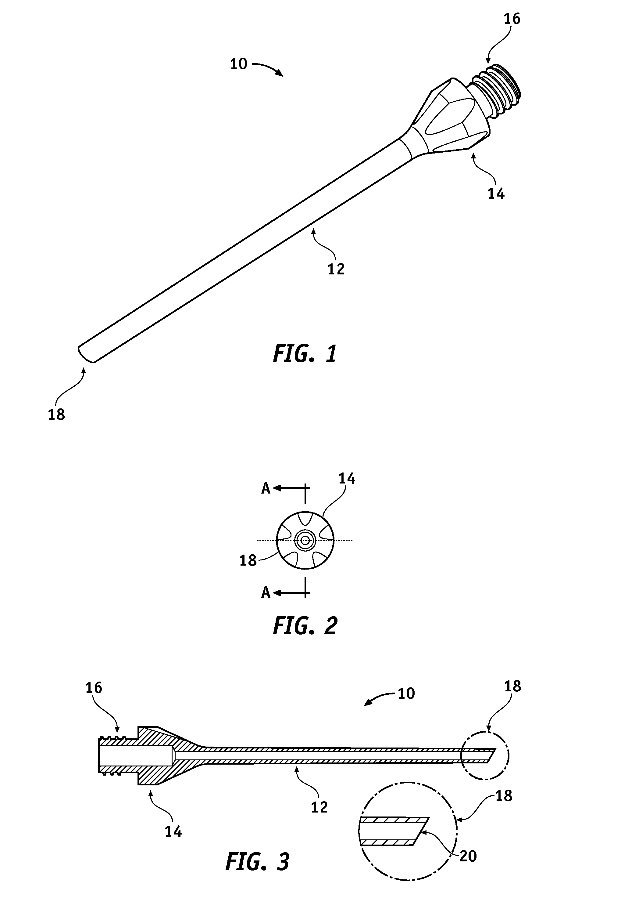
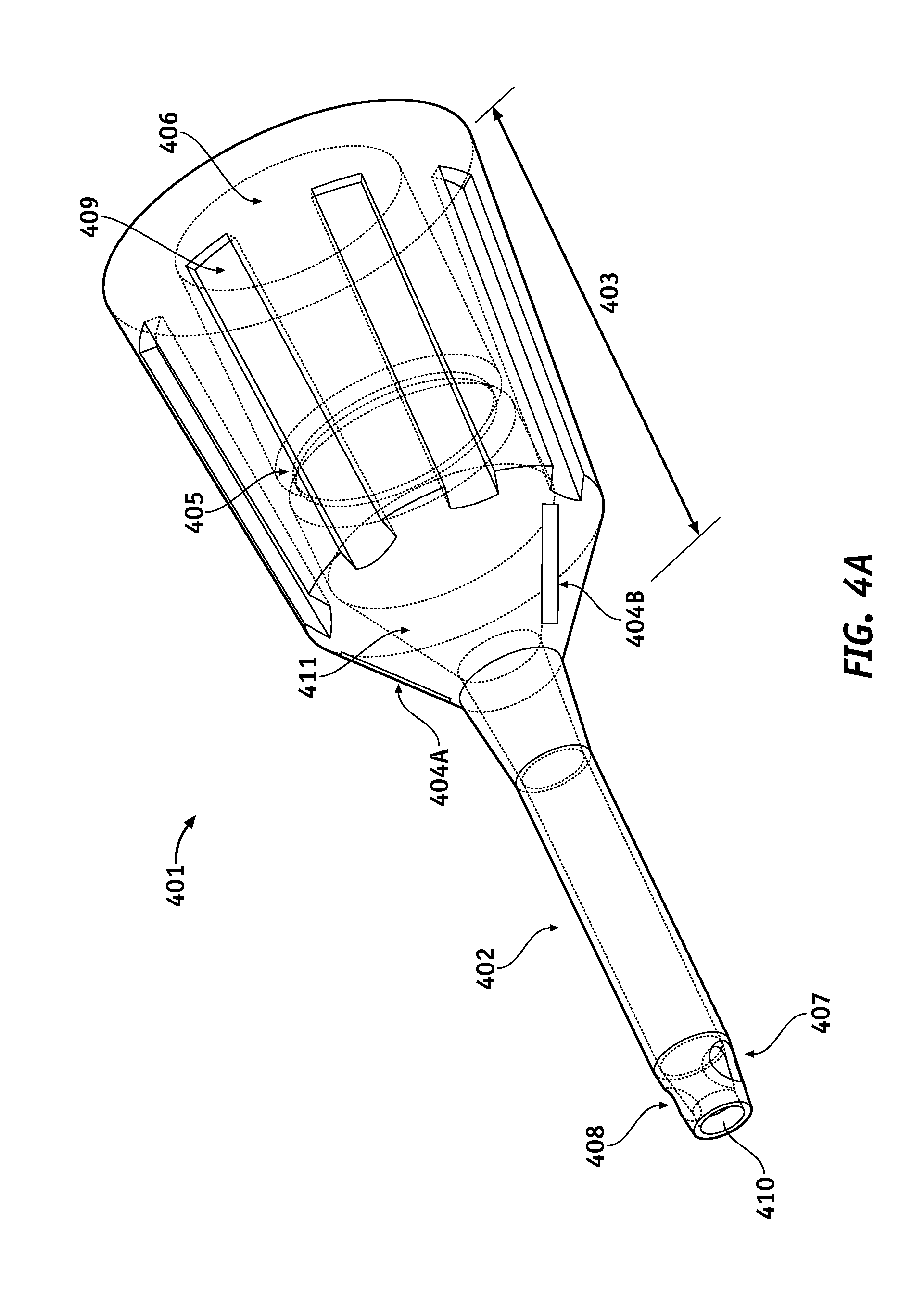
[0028]The present design is directed to a device configured for use in an ocular surgical procedure. The device, which may be a sleeve, a phacoemulsification (“phaco”) needle, a vitrectomy cutter, or similar device, comprises a proximal portion, a distal portion comprising at least one fluid opening formed at a predetermined orientation, and at least one visual marking provided at the proximal portion at a predetermined marking orientation relative to the predetermined o...


PUM


Abstract

A device configured for use in an ocular surgical procedure is provided. The device, such as a sleeve or a needle, includes a proximal portion, a distal portion including at least one fluid opening formed at a predetermined orientation, and at least one visual marking provided at the proximal portion at a predetermined marking orientation relative to said predetermined orientation. The visual marking or markings provide a visual indication of orientation of the fluid opening when the device is employed in the ocular surgical procedure.

Description

BACKGROUND OF THE INVENTION[0001]1. Field of the Invention[0002]The present invention generally relates to fluid delivery devices employed for use with phacoemulsification needles and more specifically to orientation of such fluid delivery devices during surgical procedures.[0003]2. Description of the Related Art[0004]Phacoemulsification refers to a method of lens and cataract extraction from an eye. The procedure includes an ultrasonically vibrated needle which is inserted through a very small incision of the cornea in order to provide energy for fragmenting the lens and cataract which then can be aspirated and removed through the incision.[0005]The needle is supported by a handpiece interconnected with a console which provides electrical power to the handpiece as well as a supply of irrigation fluid and a vacuum source for aspiration of fragmented tissue and liquids.[0006]Certain current handpieces can provide fluid to the eye during the surgical procedure. In order to facilitate ...

Claims


Application Information

Patent Timeline
Patent Type & Authority Applications(United States)
IPC IPC(8): A61F9/007
CPCA61B2019/4857A61F9/00736A61M2210/0612A61M2205/583A61M2205/6081A61M1/0084A61B2090/0811A61M1/85A61M2205/6018A61B2090/0807A61M2205/6036A61M2205/6045A61B2017/320084A61M2205/6063A61F9/00745
Inventor GERG, JAMES
Owner JOHNSON & JOHNSON SURGICAL VISION INC
Why Eureka
Try Eureka