[0012] A significant
advantage of the present invention is that it allows for the simply configured tape guides of the invention to be used independent of the type and size of different components to be handled and, in turn, of the configuration of the component tape on which they are provided. The invention also entails a facilitated handling in connection with the use of this type of component tape guides, since a minimum of auxiliary equipment and extra labor is required for handling a vast number of different component tapes and components.
[0013] It should be noted that the following description refers to component tapes having the same component tape width.
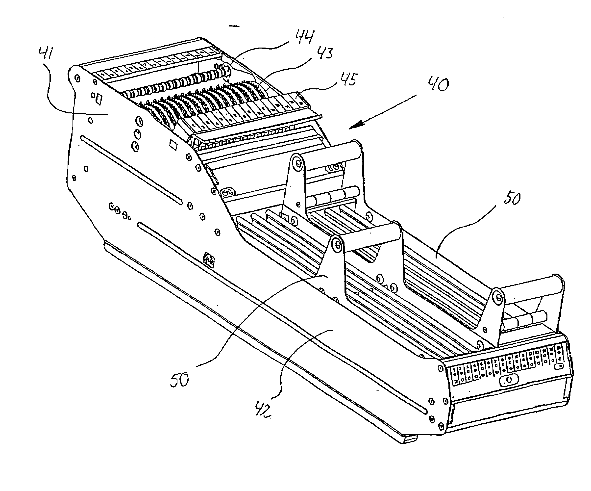
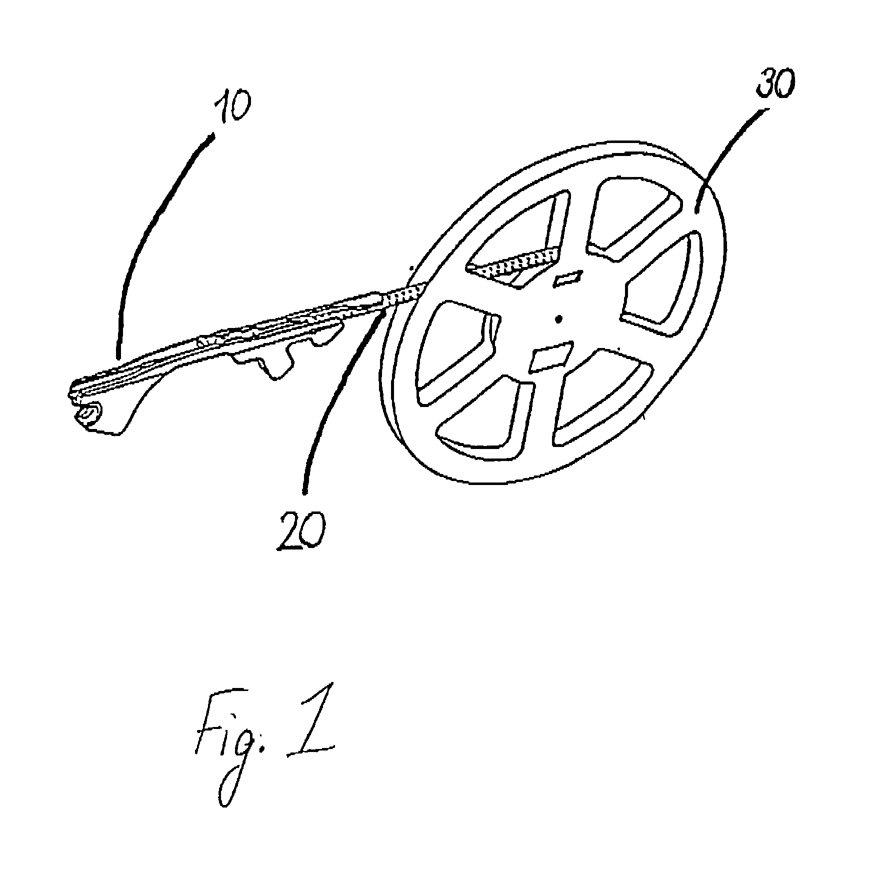
[0014] According to a first aspect of the present invention, there is provided a system for handling components at a component mounting machine, which system comprises a plurality of component tapes of a given component tape width, each component tape, in turn, comprising a carrier tape and a cover tape, and carrying components that are positioned in sequence on the carrier tape and are covered by the cover tape, wherein the component tapes have different configurations depending on the carried components. The system also comprises a plurality of component tape holders, each holder being arranged for holding a component tape, and a plurality of tape guides arranged for receiving a component tape of said given component tape width and for bringing said component tape in position for feeding of the component tape and for picking components from the component tape at said component mounting machine, wherein said tape guides are releasably mountable at said component mounting machine, preferably in a component
magazine. Each tape guide is provided with a component
exposure device, the exposure device exposing a component at a picking position by at least partly removing or displacing the portion of the cover tape covering said component. Also, said tape guides are divided into sub-sets of tape guides, wherein the tape guides of all sub-sets have a similar geometrical outline and basic configuration, and wherein the tape guides of each sub-set have component exposure devices of a same design which is different from the designs of the component exposure devices of the tape guides of the other sub-sets, the design of the component exposure devices within each sub-set of tape guides being dependent on said configurations of the component tapes intended for said sub-set of tape guides.
[0015] At present, there are a wide variety of different configurations for component tapes of the same component tape width. The thickness of the component tapes may vary, the size of the compartments may vary according to the components of the tape, the positions of the compartments, or rather the distance between the compartments, may also vary, as may the features of the cover tapes, both as to the positions of the
adhesive or fused areas, as well as the width of the cover tape. However, the majority of components are provided on component tapes having a width selected from a few standardized component tape widths. For instance, at present approximately 80 percent of the components packed in component tapes and used in the circuit board assembling industry are provided on component tapes of 8 mm width.
[0016] Generally, each compartment contains one component only. Since the size of the components can vary greatly in component tapes of the same width, the size of the compartments varies accordingly. There must be sufficient space for accommodating the component, at the same time as there is a desire for the compartments to be small for limiting the movement of the component within the compartment, and for providing as many compartments as possible on the component tape. The difference in size refers to both the length and width of the compartment, as well as to the depth of the compartment. The depth of the compartment may also affect the overall thickness of the component tape. According to
standardization protocols, the transversal center of each compartment is positioned at a defined distance from the lateral edge of the component tape. Thus, the distance from the lateral edge of the compartment to the lateral side of the component tape varies in accordance with the width of the compartment. Generally, the areas where the cover tape is attached to the carrier tape are positioned immediately adjacent to the lateral side of each compartment, i.e. between the compartment and the lateral edges of the component tape. For component tapes with very small compartments, these areas may be provided slightly spaced apart from the edges of the compartments. Furthermore, the width of the cover tape is generally the same for component tapes of the same width. However, there are exceptions where the width of the cover tape is varied within the same component tape width, essentially in correspondence with the width of the compartments.
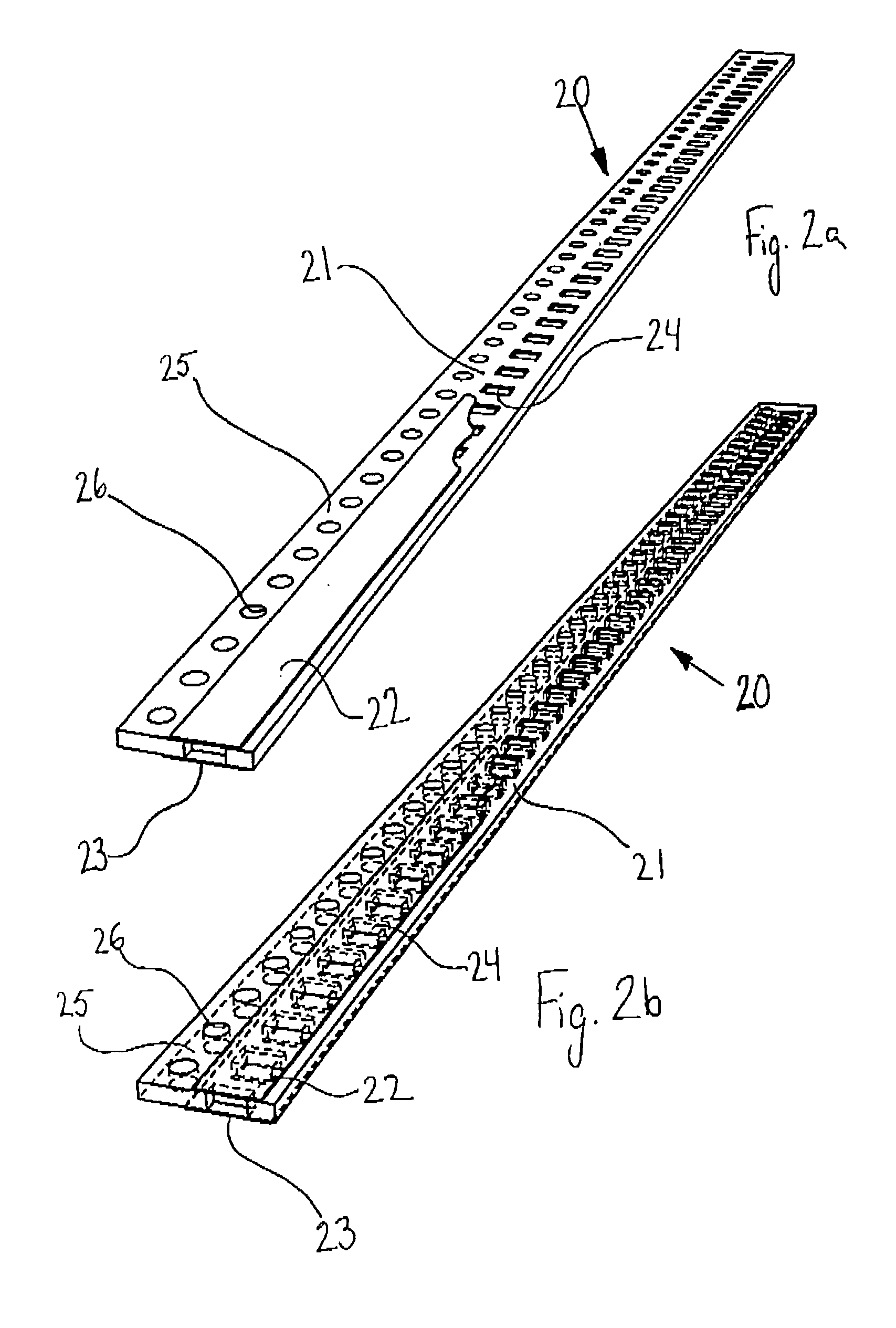
[0017] The exposure device of a tape guide of the invention exposes a component by at least partly removing or displacing from the carrier tape the portion of the cover tape that covers the component. Preferably, this is performed by providing the exposure device with a separating portion that is brought into engagement with the component tape between the cover tape and the carrier tape, thus lifting the cover tape from the carrier tape. According to the present invention, the design of the exposure device is varied in accordance with the configuration of the component tape, in such a manner that the separating portion is brought into engagement with the component tape at the correct position. Thus, each tape guide is provided with an exposure device of a specific type adapted to the configurations of the component tapes for which the tape guide is intended. Consequently, the tape guides may be divided into sub-groups or sub-sets of tape guides, wherein the tape guides of all sub-sets have the same geometrical outline and basic configuration, while the design of the exposure devices of the tape guides varies between the tape-guides of different sub-sets. In other words, all tape guides within the same sub-set are adapted for handling the same multitude of types and configurations of component tapes with the same width.

