Stent-within-stent arrangements

a technology of stents and stents, applied in the field of stent arrangements, can solve the problems of metal stents remaining patent longer, stents that cannot expand, and stents that are rapidly blocked,

Inactive Publication Date: 2011-04-21
WILSONCOOK MEDICAL
View PDF9 Cites 214 Cited by
  • Summary
  • Abstract
  • Description
  • Claims
  • Application Information

AI Technical Summary

Benefits of technology

In a second aspect, a medical device for dilation of a body lumen is provided. The device comprises an outer stent comprising outer struts spaced apart to form outer spaces therebetween. An inner stent is also provided. The inner stent comprises inner struts spaced apart to form inner spaces therebetween. At least a portion of the inner stent is slidably interfitted within the outer stent. An interlocking element fixates the inner stent within the outer stent. At least a portion of the inner struts occupy the outer spaces of the outer struts to substantially prevent tissue in-growth therethrough.

Problems solved by technology

However, plastic stents are not expandable, thereby possessing a fixed diameter.
However, such a small diameter stent rapidly becomes clogged within the biliary and pancreatic ducts, thereby requiring replacement every three months, or even sooner.
Consequently, such metal stents remain patent longer than plastic stents, averaging perhaps 6 months before clogging.
However, the capability of larger diameter stents to collapse into endoscopic delivery systems necessitates mesh or wire geometries that incur tissue in-growth, commonly known as endothelialization, thereby oftentimes rendering the stent permanent and impossible to remove.
Therefore, even when a retrievable metal stent has been employed, it may not be possible to remove it without damaging surrounding tissues.

Method used


Image

  • Stent-within-stent arrangements
  • Stent-within-stent arrangements
  • Stent-within-stent arrangements

Examples


Embodiment Construction

The invention is described with reference to the drawings in which like elements are referred to by like numerals. The relationship and functioning of the various elements of this invention are better understood by the following detailed description. However, the embodiments of this invention as described below are by way of example only, and the invention is not limited to the embodiments illustrated in the drawings. It should also be understood that the drawings are not to scale and in certain instances details, which are not necessary for an understanding of the present invention, have been omitted such as conventional details of fabrication and assembly.

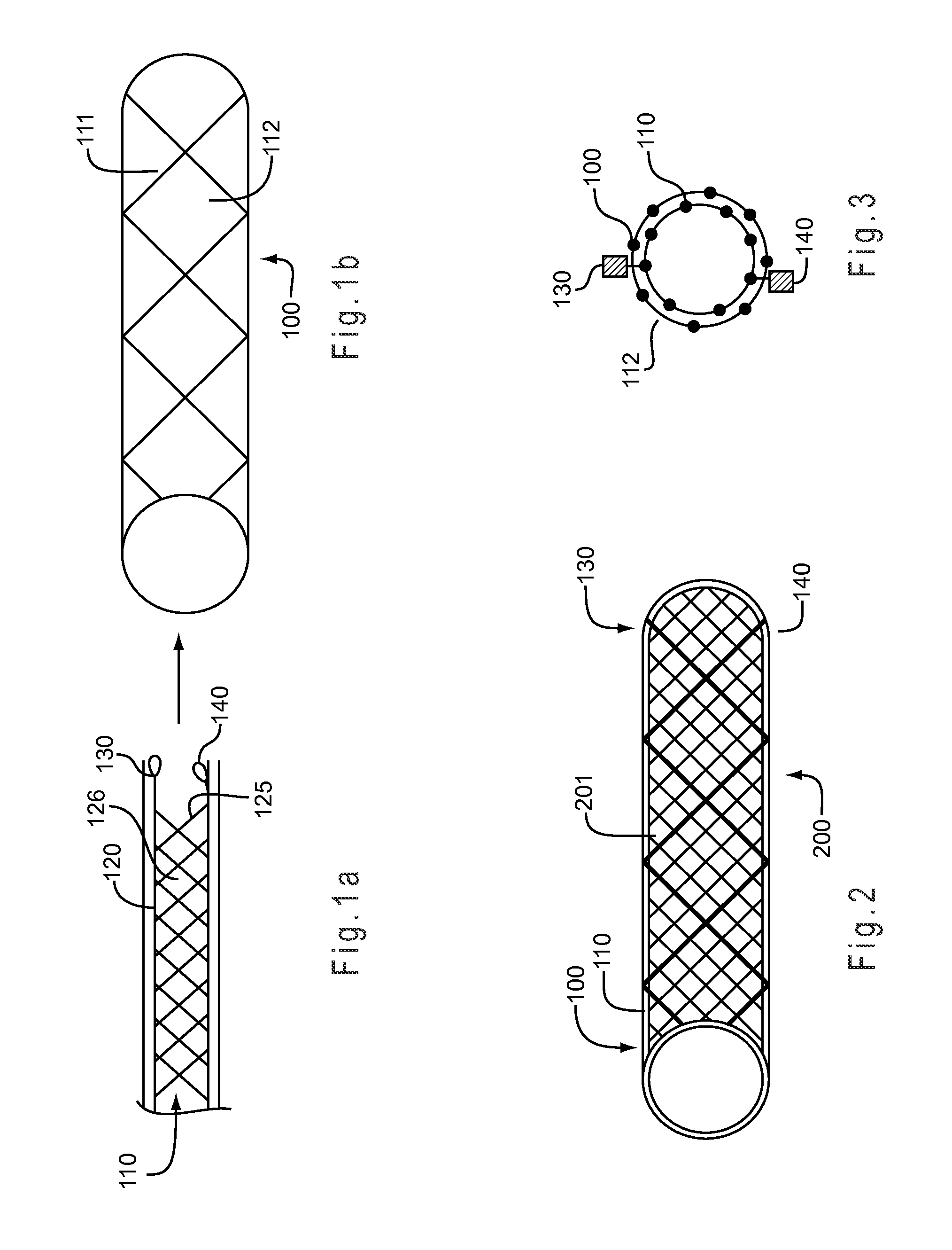
FIG. 1a illustrates a side view of an inner stent 110 that is to be deployed and anchored within an outer stent 100. The outer stent 100 is shown in FIG. 1b as deployed and in its expanded state. The outer stent 100 has struts 111 which create a mesh design. The struts 111 are spaced apart in the expanded state so as to create in...


PUM


Abstract

A variety of stent arrangements are described in which multiple stents expand and coordinate to block the spaces between the struts of the outer stent to create a tubular stent not prone to tissue in-growth. One or more stents are selectively positioned within an outer stent such that the struts of the one or more stents at least partially fill the openings of the outer stent. Alternatively, the one or more stents may be permanently affixed to the outer stent to produce a stent arrangement in which the openings between the struts of the outer stent are blocked by the struts of the one or more stents.

Description

BACKGROUNDThe present invention relates generally to medical devices and more particularly to stent arrangements that are used to dilate narrowed portions of a body lumen.Stents are widely used in the medical profession to enlarge, dilate or maintain the patency of narrowed body lumens. A stent may be positioned across a narrowed region while the stent is in a compressed state. The stent may then be expanded in order to widen the lumen.Stents used in the gastrointestinal system have been typically constructed of plastic. Plastic stents facilitate retrieval and / or replacement of the stent during a follow-up procedure. However, plastic stents are not expandable, thereby possessing a fixed diameter. Since plastic stents are frequently delivered through the working channel of an endoscope, the diameter of the working channel limits the diameter of the stent. For example, plastic stents typically have a diameter that is no greater than 11.5 French. However, such a small diameter stent ra...

Claims


Application Information

Patent Timeline
Patent Type & Authority Applications(United States)
IPC IPC(8): A61M29/00A61F2/04A61F2/90
CPCA61F2/848A61F2/852A61F2250/0063A61F2/90A61F2/88
Inventor RUCKER, BRIAN K.GAYZIK, CAROLINE M.
Owner WILSONCOOK MEDICAL
Why Eureka
Try Eureka