Method for protecting redundant data

Inactive Publication Date: 2011-04-21
INVENTEC CORP
View PDF18 Cites 18 Cited by
  • Summary
  • Abstract
  • Description
  • Claims
  • Application Information

AI Technical Summary

Benefits of technology

[0007]The present invention is directed to a method for protecting redundant data,

Problems solved by technology

However, the redundant data area is not protected according to an existing method.
When an operating system is oper

Method used


Image

  • Method for protecting redundant data
  • Method for protecting redundant data
  • Method for protecting redundant data

Examples


Embodiment Construction

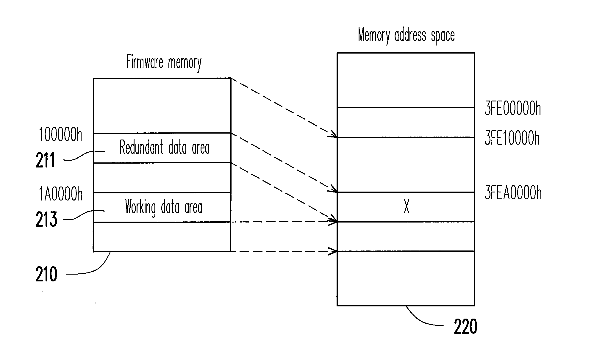
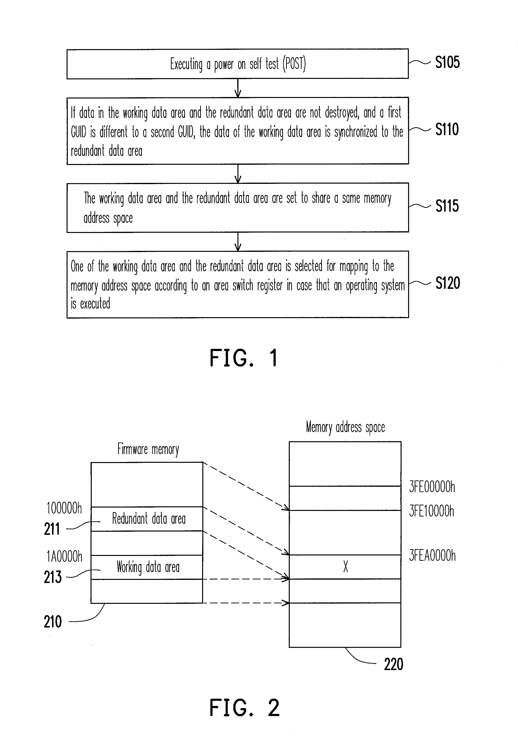
[0019]FIG. 1 is a flowchart illustrating a method for protecting redundant data according to an embodiment of the present invention. This method is adapted to a firmware memory, for example, a flash read-only memory used for storing a basic input output system (BIOS). In the present embodiment, the firmware memory includes a working data area and a redundant data area. The redundant data area serves as a backup of the working data area.

[0020]Referring to FIG. 1, first, in step S105, the BIOS executes a power on self test (POST). Here, the BIOS first initialize a system memory, so that the system memory can be accessed. Moreover, the BIOS maps the firmware memory to a memory address space below a 4G-1 address.

[0021]Next, in step S110, if data in the working data area and the redundant data area are not destroyed, and a global unique identifier (GUID) of the working data area is detected to be different to a GUID of the redundant data area, the data of the working data area is synchro...


PUM


Abstract

A method for protecting redundant data is provided. In the present invention, when a working data area and a redundant data area are not destroyed, whether global unique identifiers (GUIDs) of both the working data area and the redundant data area are the same is determined when a power on self test (POST) is executed. If the GUIDs are different, the data of the working data area is synchronized to the redundant data area. Next, the working data area and the redundant data area are set to share the same memory address space. One of the working data area and the redundant data area is selected for mapping to the memory address space in case that an operating system is executed.

Description

CROSS-REFERENCE TO RELATED APPLICATION[0001]This application claims the priority benefit of Taiwan application serial no. 98135468, filed on Oct. 20, 2009. The entirety of the above-mentioned patent application is hereby incorporated by reference herein and made a part of this specification.BACKGROUND OF THE INVENTION[0002]1. Field of the Invention[0003]The present invention relates to a boot method. More particularly, the present invention relates to a method for protecting redundant data.[0004]2. Description of Related Art[0005]Generally, when a computer system is booted, a basic input output system (BIOS) thereof is first started to execute a power on self test (POST). After the POST is completed, the BIOS integrate data related to the computer system into a table, and write the table into a main memory. The data related to the computer system is for example, information of a manufacturer, a BIOS manufacturer, a computer serial No., a universal unique identifier (UUID), etc., whi...

Claims


Application Information

Patent Timeline
IPC IPC(8): G06F12/16
CPCG06F11/1417G06F12/1433G06F11/20G06F11/1666
Inventor LU, YING-CHIHWANG, YU-HUI
Owner INVENTEC CORP
Why Eureka
Try Eureka