[0010]Usually, the pressure of the striker spring contacting the firing pin or the firing-pin piece in the series provided according to the invention for roller bodies contacting each other is derived via the control body. Among other things, through the friction prevailing between the roller bodies, the force that is provided by the tensioned striker spring and usually lies in the range of 100 to 110 Newton, that is, 10 to 11 kg, can be reduced to a very low trigger weight. In preferred embodiments, it is possible to achieve trigger weights of 1 Newton or 100 grams and below with releasing devices constructed according to the invention. One special
advantage of the releasing device according to the invention, however, is also the quickness with which the motion released by the release trigger can be transferred via the series of roller bodies and thus via the transmission mechanism constructed according to the invention to the control body and thus to the firing pin or the firing-pin piece. Despite these advantages, releasing devices according to the invention can be produced more easily due to their simpler structure and thus also more economically than the lever-transmission mechanisms known in the prior art. Another
advantage of the invention lies in that releasing devices according to the invention could also be realized with very small spatial requirements, that is, can be realized in a small structural size.
[0011]For the sake of completeness, it is noted that the releasing devices according to the invention could be combined with very many different bolt actions for firearms known in the prior art. The control body could here act directly or also indirectly by via the intermediate connection of additional parts on the firing pin or the firing-pin piece. Releasing devices according to the invention, however, do not necessarily have to be used in firearms. If a releasing device for a firing pin or a firing-pin piece is also needed at another position, then this could be constructed according to the invention.
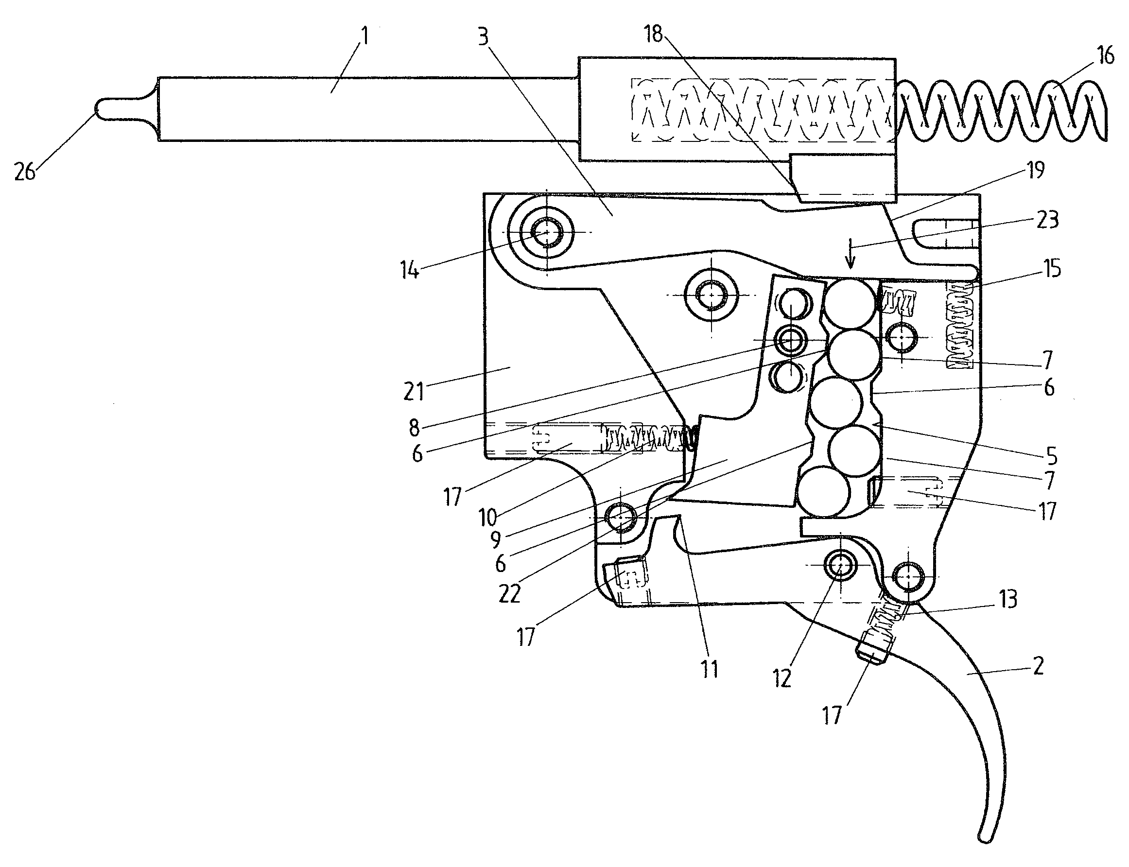
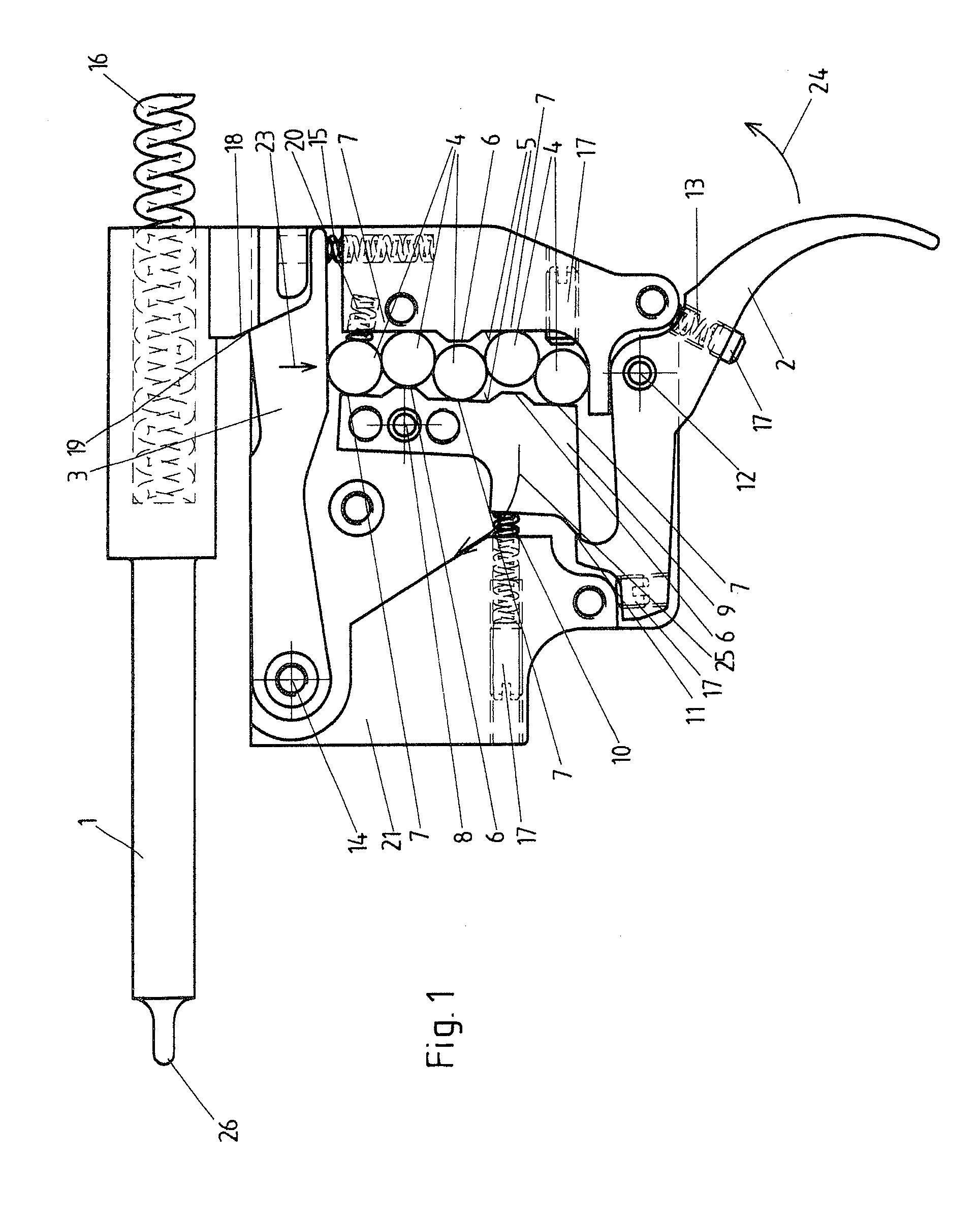
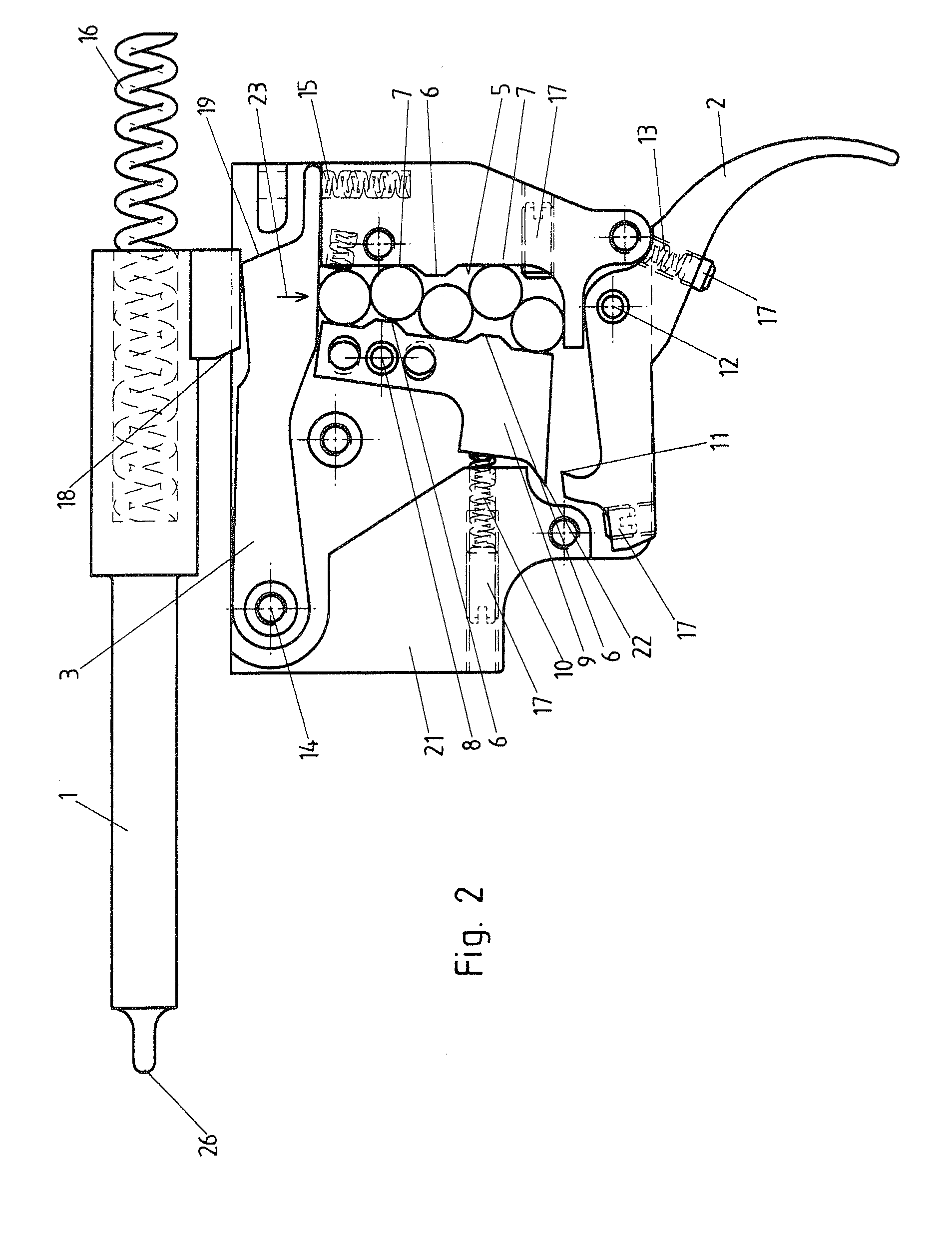
[0012]Favorably it is provided that the roller bodies forming the series are arranged on behind the other and each roller body contacts exactly two adjacent roller bodies, apart from the first and last roller bodies of the series.
[0013]Especially preferred embodiments of the invention provide that every two successive and / or contacting roller bodies of the series of roller bodies are arranged offset relative to each other. In this sense, the roller bodies of the series should not lie one behind each other exactly in a line, but instead should be arranged offset somewhat relative to each other especially viewed in the direction of the series with respect to its centers or center axes. Furthermore, it is preferable in the sense of the invention if the series of roller bodies is arranged in a
transmission channel defined by channel walls. The distance of opposing channel walls should here be at least somewhat greater than the
diameter of the roller bodies. Preferably, however, the distance of opposing channel walls is less than twice the
diameter of each roller body. In this way it can be guaranteed that the roller bodies are arranged one behind the other, in particular, despite their offset. Preferably it is further provided that each roller body contacts at least one of the channel walls.
[0014]Through the offset of the roller bodies relative to each other, however, through their contact on at least one channel wall, the forces of the striker spring introduced via the control body onto the series of roller bodies are reduced in an especially good way, so that, overall, a very low trigger weight can be realized for the releasing device according to the invention. Preferably, it is provided here that the balls do indeed contact each other, the channel walls, and the control body, but otherwise move freely, that is, they are not also further connected to each other. In particular, in order to maintain or to specify the offset of the roller bodies relative to each other, preferred embodiments of the invention are provided such that at least one of the channels walls has at least one wall section projecting in the direction toward the channel interior, advantageous a series of alternating wall sections projecting in the direction toward the channel interior and recessed in the opposite direction.
[0015]In order to be able to transfer the motion of the release trigger generated by the activation by hand or with one finger to the series of roller bodies, especially preferred embodiments of the invention provide that at least one sub-area of at least one of the channel walls is constructed as a rocker that can pivot about at least one rocker pivoting axis. Here a locking piece could be arranged on the release trigger, wherein the rocker can be fixed in a first position and can be released in at least one released position. The rocker can be reset, in particular, in a releasing device released by the pressure of the striker spring, in that the rocker is spring-loaded from at least one rocker pull-back spring that is advantageously adjustable in its
spring force, advantageously outside of the rocker pivoting axis.

