Front vehicle-body structure of vehicle

a front-side frame and vehicle body technology, applied in the direction of roofs, jet propulsion mounting, transportation and packaging, etc., can solve the problem that the above-described restraint of the vertical deformation of the front side frame may not be sufficient to achieve the proper bending of the front side frame, and achieve the effect of reducing the collision load against passengers

Inactive Publication Date: 2011-04-28
MAZDA MOTOR CORP
View PDF2 Cites 55 Cited by
  • Summary
  • Abstract
  • Description
  • Claims
  • Application Information

AI Technical Summary

Benefits of technology

[0006]An object of the present invention is to provide a front vehicle-body structure of a vehicle which can properly promote bending of the front side frame at its bending portion when the collision load acts in the vehicle frontal collision so that the collision load against passengers can be decreased securely.

Problems solved by technology

However, only the above-described restraint of the vertical deformation of the front side frame may be insufficient for obtaining the proper bending of the front side frame.

Method used


Image

  • Front vehicle-body structure of vehicle
  • Front vehicle-body structure of vehicle
  • Front vehicle-body structure of vehicle

Examples


embodiment 1

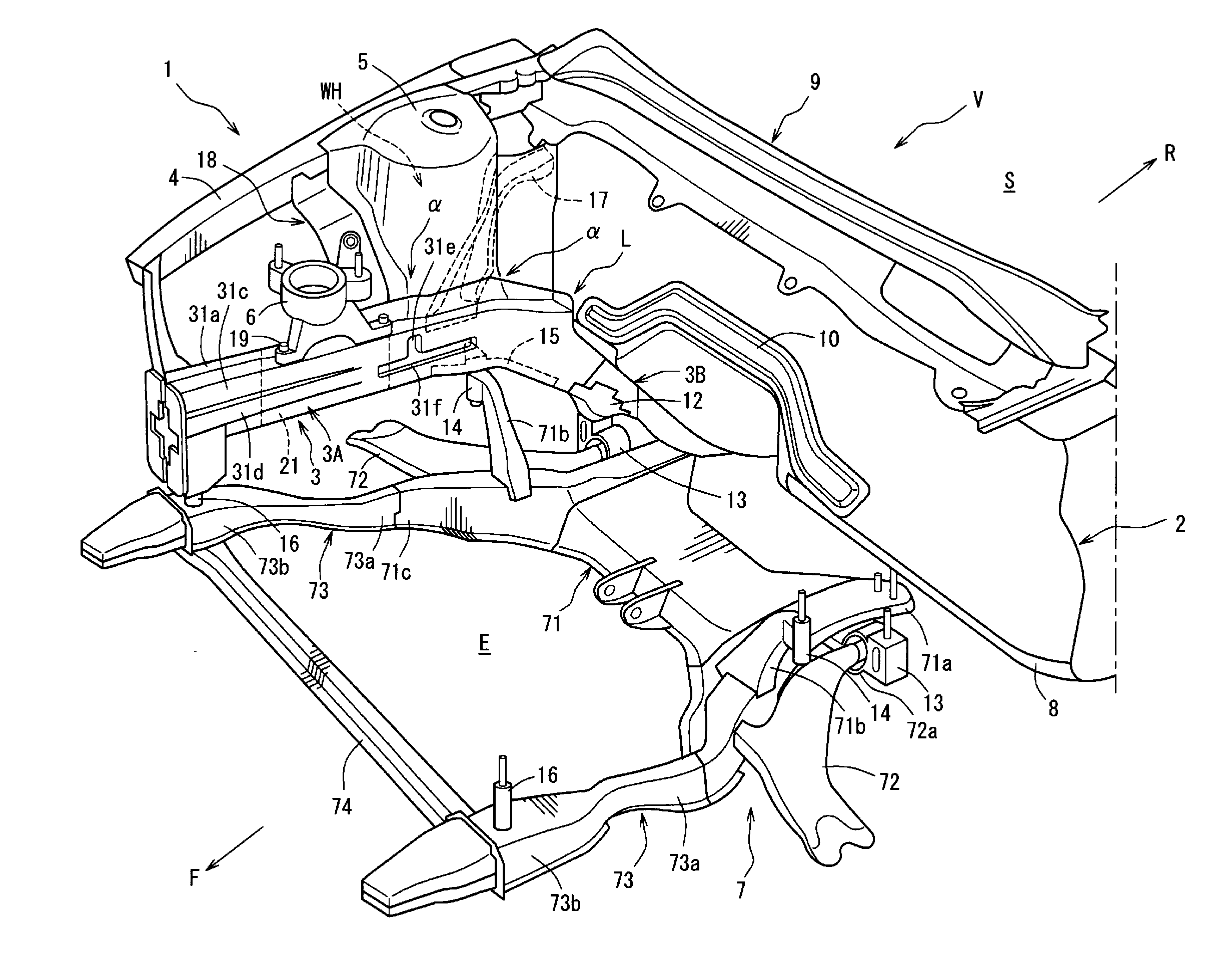
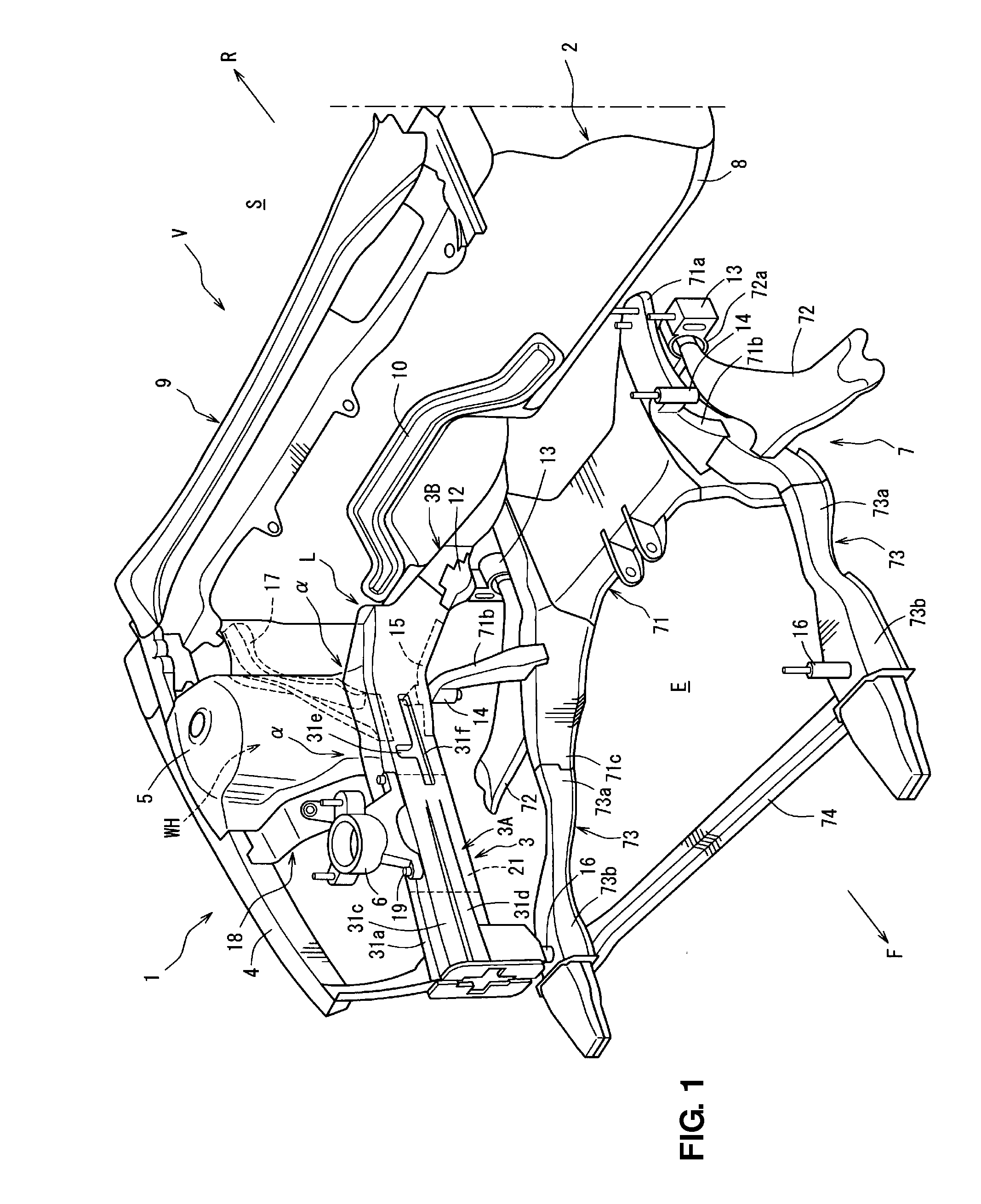
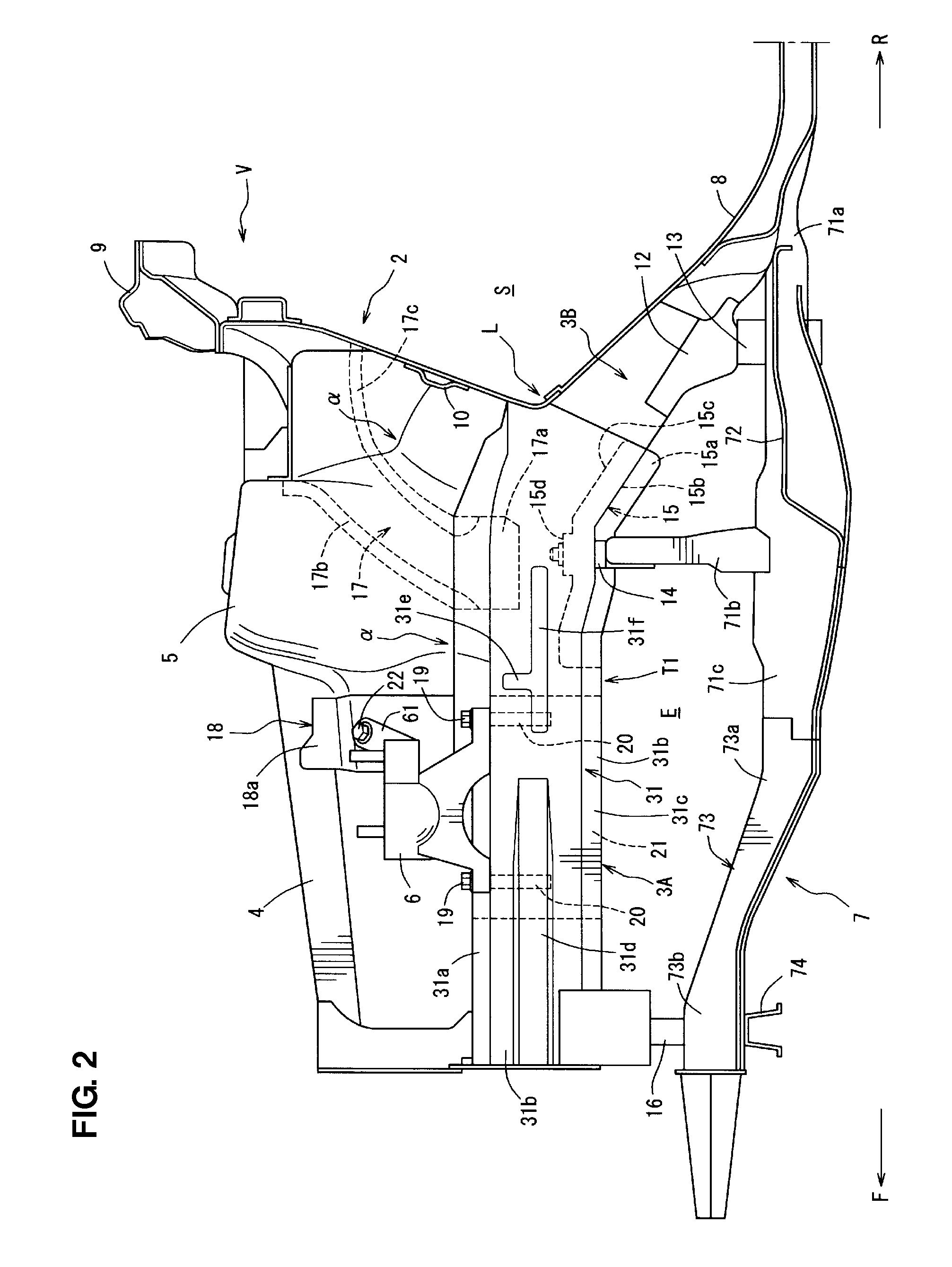
[0032]FIG. 1 is a perspective view of a front vehicle-body structure of a vehicle according to a first embodiment of the present invention, when viewed from above and front. FIGS. 2 and 3 are side views of the front vehicle-body structure of a vehicle (FIG. 2 is a side view, when viewed outwardly from the inside of the vehicle, and FIG. 3 is a side view, when viewed inwardly from the outside of the vehicle). Herein, in the figures, an arrow (F) shows a vehicle front direction, an arrow (R) shows a vehicle rear direction, an arrow (IN) shows a vehicle inward direction, and an arrow (OUT) shows a vehicle outward direction.

[0033]A front vehicle body 1 of a vehicle V comprises, as shown in FIGS. 1 and 2, a dash panel 2 which partitions a vehicle room S from an engine room E in a vehicle longitudinal direction at a front of the vehicle body 1, a pair of front side frames 3 which is connected to a front side of the dash panel 2 and extends in the vehicle longitudinal direction, a pair of ...

embodiment 2

[0095]In a second embodiment of the present invention, a reinforcing member 115 shown in FIG. 12 is applied instead of the reinforcing member 15 shown in FIG. 4 of the first embodiment. That is, the height position of a horizontal plate portion 115b which is continuous from a first vertical plate portion 115a, which corresponds to the first vertical plate portion 15a, is set to be higher than that of the horizontal plate portion 15b of the reinforcement 15 of the above-described first embodiment. Further, a second vertical plate portion 115c which is continuous from the horizontal plate portion 115b contacts a vertical portion of the inner panel body 31c via face contact. Thus, a second closed cross section X is formed in the closed cross section 30 of the front side frame 3. In FIG. 12, the same structure elements as those of the first embodiment are denoted by the same reference numerals, specific descriptions of which are omitted here.

[0096]In the second embodiment, a through hol...


PUM


Abstract

Part of a front side frame is configured to be deformed so as to bend outwardly, in a vehicle width direction, by a collision load in a vehicle frontal collision. A sub frame provided at a lower portion of a front vehicle body is joined to the front side frame via a reinforcement. A front portion of the reinforcement is located at a position which corresponds to a bending portion of the front side frame which is to be deformed so as to bend outwardly, in the vehicle width direction, by the collision load in the vehicle frontal collision. Accordingly, the bending of the front side frame at its bending portion when the collision load acts in the vehicle frontal collision can be promoted, so that the collision load against passengers can be decreased securely.

Description

BACKGROUND OF THE INVENTION[0001]The present invention relates to a front vehicle-body structure of a vehicle, in which part of a front side frame which is connected to a front side of a dash panel and extends in a vehicle longitudinal direction is configured to be deformed so as to bend outwardly, in a vehicle width direction, by a collision load in a vehicle frontal collision.[0002]Conventionally, a structure in which in order to decrease a collision load against passengers in a vehicle collision, the front side frame extending in the vehicle longitudinal direction in front of the dash panel bends in the vehicle width direction and thereby absorbs collision energy of the vehicle collision is known.[0003]Japanese Patent Laid-Open Publication No. 2009-137380, for example, discloses a vehicle-body structure in which the front side frame has a bending portion which is to be deformed so as to bend outwardly, in the vehicle width direction, by the collision load in the vehicle frontal c...

Claims


Application Information

Patent Timeline
Patent Type & Authority Applications(United States)
IPC IPC(8): B62D25/08
CPCB60K5/1216B62D21/09B62D25/088B62D21/152B62D21/11
Inventor TERADA, SAKAYUHONJI, HIROMASAFUKUSHIMA, MASANOBU
Owner MAZDA MOTOR CORP
Why Eureka
Try Eureka