Eureka AIR delivers breakthrough ideas for toughest innovation challenges, trusted by R&D personnel around the world.

Ink jet recording device and ink jet recording method

a recording device and ink jet technology, applied in the direction of printing, duplicating/marking methods, inks, etc., can solve the problems of low manufacturing efficiency, uneven nozzles, and low printing speed, and achieve high speed, reduce density unevenness, and high quality

Active Publication Date: 2011-04-28
KONICA MINOLTA INC
View PDF5 Cites 37 Cited by
  • Summary
  • Abstract
  • Description
  • Claims
  • Application Information

AI Technical Summary

Benefits of technology

[0056]According to the present invention, it is possible to provide an ink-jet recording device and an ink-jet recording method which enable to record a high quality image having small deterioration with reduced density unevenness and ink bleeding with each color when applied in multicolor printing with a single pass mode recording at high speed.

Problems solved by technology

Although the scanning method is the way which is used especially widely in a home ink-jet recording device, which makes a picture by allowing a head to go and come back several times, its printing speed is generally very low and as a result its manufacturing efficiency is low.
However, although a single pass mode is a mode to print by one scanning (relative displacement of a head with respect to a recording medium) as mentioned above, and it can print at high speed and it is excelled in manufacturing efficiency, the jetted ink from the nozzle may produce unevenness by the effect of conveyance and the accuracy of the nozzle, which will influence the image quality to a large extent.
However, when a single pass mode ink-jet recording is employed to perform multicolor printing, after ejection of the ink, the subsequent fixation or solidification of the ejected ink may not be completed, as a result, it was found out that there will occur “bleeding” which is produced by mixing inks having different colors.
However, by using this technology, an uneven density was generated with substantially non-absorbing recording medium, and when this technology was used for multicolor printing, a large amount of bleeding was generated and it was not helpful.
When a single pass mode of multicolor printing at high speed was combined with this technology, the bleeding between each ink printed in order could not be stopped, and it was a problem.
Moreover, with this technology, the uneven density in the overlapping portion was also observed, and this technology did not bear practical use.
However, by this method, since the manufacturing process of newly applying under coat liquid is required, it is inferior to manufacturing efficiency.
Moreover, although this under coat liquid and a variety of curable inks are used in an actual field, when affinity with inks was bad, chemical reactions, such as aggregation, were also generated and there was a case where the formula change of the under coat liquid was required, and not all bleeding was controlled well, and actual use including the manufacturing efficiency in the field was not able to be achieved.

Method used


Image

  • Ink jet recording device and ink jet recording method
  • Ink jet recording device and ink jet recording method
  • Ink jet recording device and ink jet recording method

Examples


examples

[0230]Hereafter, although the effects of the present invention will be illustrated based on the examples, the present invention is not limited to these.

[0231]A cationic polymerizable UV curable ink was used as an ink. The viscosities were 5 mPa·s and 10 mPa·s for Y, M, C and K each color (measured value at 50° C.), and the surface tension was about 28 dyn / cm2 (measured value at 25° C.).

[0232]In addition, although “parts” or “%” is used in the following experimental description, as long as there is no notice in particular, they represent respectively “weight parts” or “weight %”.

>

[Preparation of Dispersion Liquid A]

[0233]The following compounds each were put into a stainless steel beaker, and they were stirred to melt for 1 hour, while heated on a hot plate at 65° C.

PB821 9 parts(dispersing agent, made by Ajinomoto Fine-Techno Co., Inc.)OXT221 (oxetane compound, made by Toagosei Co., Ltd.)71 parts

[0234]After cooling to room temperature, 20 parts of Pigment Black 7 (#52 made by Mitsub...

example 5

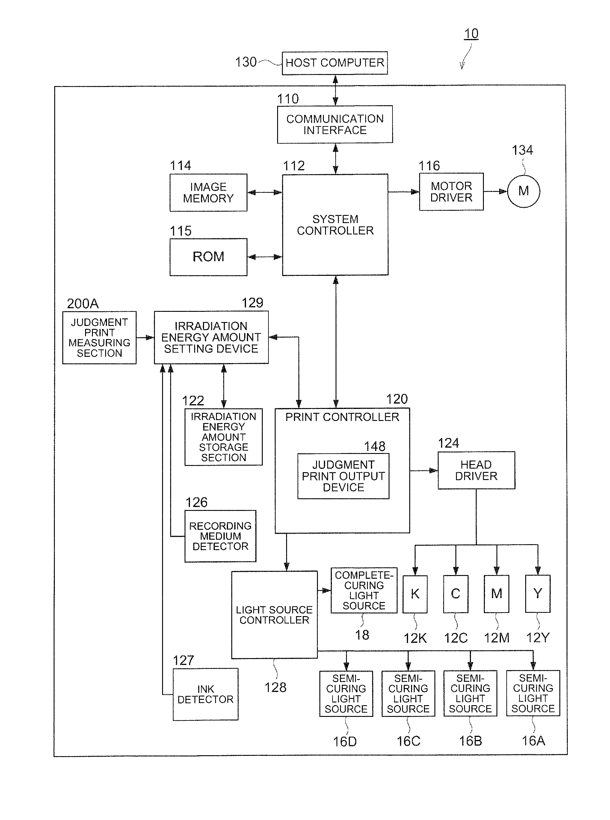
[0268]After printing R0 and R judgment prints, the controller was set with the target value of R / R0=0.67, and the controller controlled automatically. First, using the ink of Example 2, R0 and R judgment prints were printed. Then, they were automatically subjected to take pictures with a microscope in the judgment print measuring section 200A, and R0, R, and its ratio were measured. After that, it was acquired the correlation of the amount of irradiation energy of semi-curing and R / R0 shown in FIG. 7. And 10 mJ / cm2 was automatically set up for the amount of irradiation energy of half-curing, and the same evaluations as Example 2 were performed.

example 6

[0269]R0 and R judgment prints were printed. R0, R, and its ratio were measured in the same manner as in Example 5, except that the measurement was done by reading the R0 and R judgment prints with a scanner. After that, it was acquired the correlation of the amount of irradiation energy of semi-curing and R / R0 shown in FIG. 7. And 10 mJ / cm2 automatically set up for the amount of irradiation energy of half-curing, and the same evaluations as Example 2 were performed.

[0270]The evaluation results are shown in Table 2.

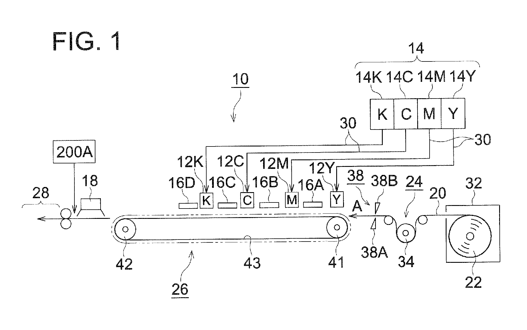
TABLE 2Irradiated energyIrradiated energyamount of semi-Irradiated energyamount of semi-Viscosity Viscosity curing light amount of semi-curing light of C inkof K inksource 16Ccuring light sourcesource 18R0RUnevenOverall(mPa · s)(mPa · s)(mJ / cm2)16D (mJ / cm2)(mJ / cm2)(μm)(μm)R / R0densityBleedingratingExample 1101051030052320.62BABExample 21010101030052350.67BABExample 31010501030052400.77AAAExample 410101001030052430.83BBCExample 51010101030052350.67BABExample 610101010300523...


PUM

PropertyMeasurementUnit
viscosityaaaaaaaaaa
viscosityaaaaaaaaaa
coloraaaaaaaaaa

Abstract

Provided are an inkjet recording device and an inkjet recording method for providing an image wherein concentration nonunifomiity is reduced with less ink bleed between inks of different colors, in high speed multicolor printing of single path system. In the device and the method, a conditional expression of 0.6≦R / R0≦0.9 is satisfied, where, R is a dot radius of a second ink jetted on a first ink which is jetted on the recording medium and semi-cured by a beam applied, and R0 is a dot radius of the second ink directly jetted on the recording medium.

Description

TECHNICAL FIELD[0001]The present invention relates to an ink-jet recording device and an ink-jet recording method. More specifically, the present invention relates to an ink-jet recording device of a single pass mode which is provided with a semi-curing light source to irradiate with an active energy ray. The present invention relates to an ink-jet recording device which can carry out multicolor printing using curing reaction with an active energy ray, and it relates to an ink-jet recording method.BACKGROUND[0002]In recent years, the ink-jet recording method has been applied to various printing fields such as photography, various kinds of printings, and special printings such as marking and color filters because the ink-jet recording method can produce an image simply and at lower cost and more easily compared with a gravure printing method. Particularly, in the field of ink-jet recording method, an image quality almost equal to a silver halide photograph can be obtained by the foll...

Claims


Application Information

Patent Timeline
Patent Type & Authority Applications(United States)
IPC IPC(8): B41J2/01B41J2/21
CPCB41J2/2146C09D11/30B41J11/002B41M5/0064B41M7/0081B41M5/0047C09D11/101B41J11/0021B41J11/00214B41J11/00216B41J11/00212
Inventor KOBAYASHI, HIDEYUKIMAKITA, MASAHIROKURAMOCHI, SHOUHEI
Owner KONICA MINOLTA INC
Why Eureka
Eureka Blog
Learn More