

Output image adjustment for image data
a technology of image data and output image, applied in the field of processing image data, can solve the problems of failure to reproduce the shooting environment, auto adjustment of image quality by image processing application program, etc., and achieve the effect of favorable image processing results
Inactive Publication Date: 2011-04-28
NAKAMI YOSHIHIRO +1
View PDF13 Cites 10 Cited by
- Summary
- Abstract
- Description
- Claims
- Application Information
AI Technical Summary
Benefits of technology
[0006]The object of the present invention is thus to solve the problems discussed above and to execute adequate image processing for shooting conditions of image data and thereby ensure favorable results of the image processing.
[0008]The image processing device as the first application of the invention has the image processing module that executes the image processing of the image data, based on the shooting condition relating to the lightness in shooting. The image processing is thus executable by taking into account the lightness in shooting. This arrangement ensures execution of the effective image processing to reduce the noise level, which is a lightness-related factor, and gives a desirable result of the image processing expected at the time of shooting.
[0010]In the image processing device as the first application of the invention, the shooting condition relating to the lightness of the subject of shooting may be at least one of an ISO speed, a shutter speed, a gain control level, and a CCD pixel size. The image processing module may heighten the noise reduction level with any of an increase in ISO speed, a decrease in shutter speed, an increase in gain control level, and a decrease in CCD pixel size. As is known in the art, the ISO speed (sensitivity), the shutter speed, and the CCD pixel size are closely related to the occurrence of noise. The occurrence of the noise is enhanced in general with an increase in ISO speed, a decrease in shutter speed, an increase in gain control level, or a decrease in CCD pixel size. The above arrangement thus efficiently reduces the noise occurrence.
[0011]In the image processing device as the first application of the invention, the image processing module may analyze lightness of the image data and set an initial value of the noise reduction level. This arrangement ensures execution of noise reduction, based on the lightness of the image data.
[0013]The image processing device in the second application of the invention utilizes the shooting conditions relating to the use or non-use of strobe light and the focal length to execute the background processing of the target of shooting. This arrangement desirably improves unnatural output results arising in the background of the target of shooting, due to the use of strobe light.
[0015]The image processing device in the third application of the invention utilizes the shooting condition relating to the image compression ratio to change the noise reduction level for execution of the image processing. This arrangement ensures adequate noise reduction for each pixel according to the image compression ratio, which is related to the noise level.
Problems solved by technology
Auto adjustment of the image quality by an image processing application program may fail reproduction of the shooting environment.
Method used
View moreImage
Smart ImageViewing Examples

Examples
first embodiment
B. Image Processing Executed by Image Processing Device in First Embodiment
second embodiment
C. Image Processing Executed by Image Processing Device in Second Embodiment
third embodiment
D. Image Processing Executed by Image Processing Device in Third Embodiment
Login to View More PUM
 Abstract
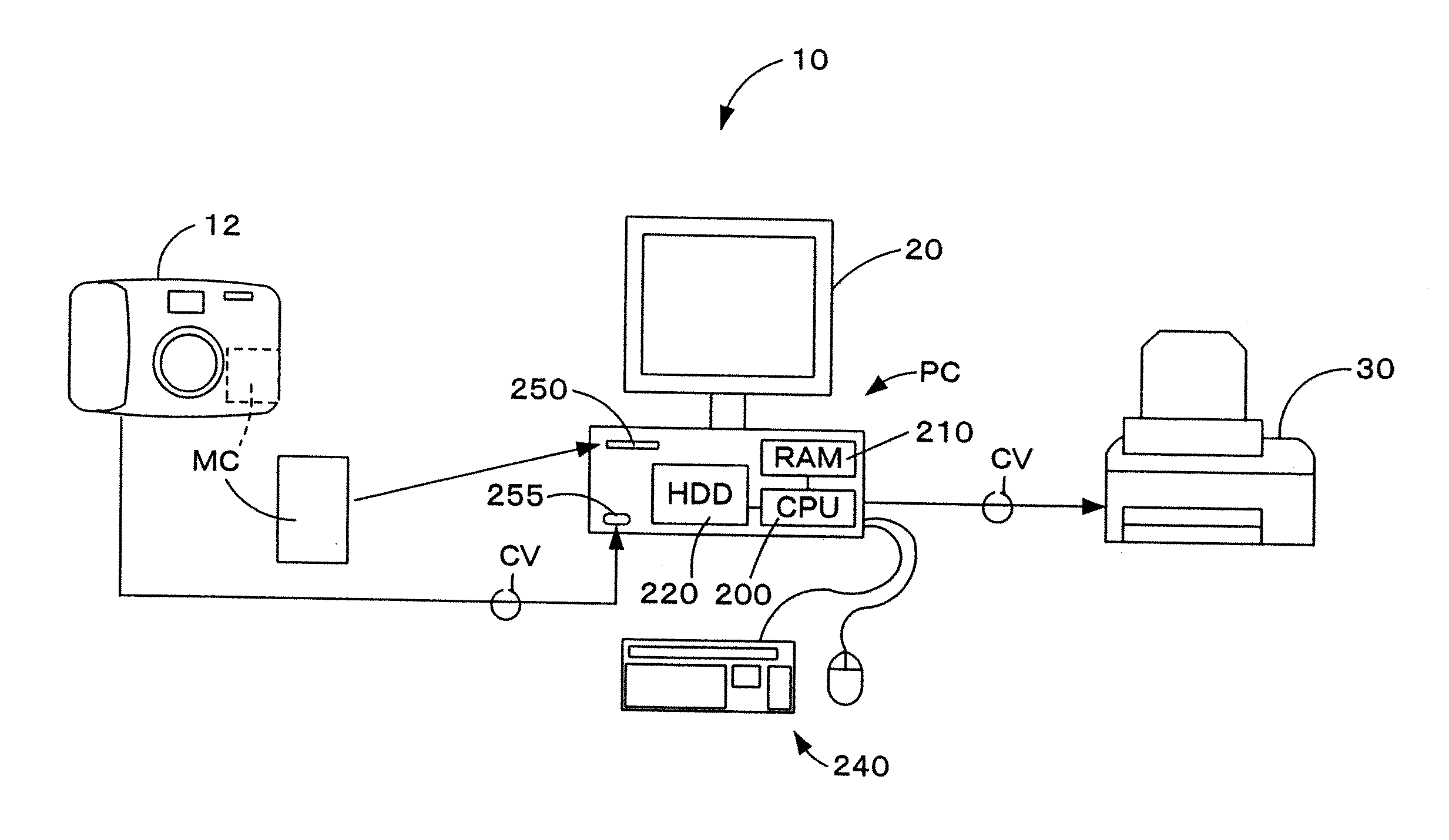
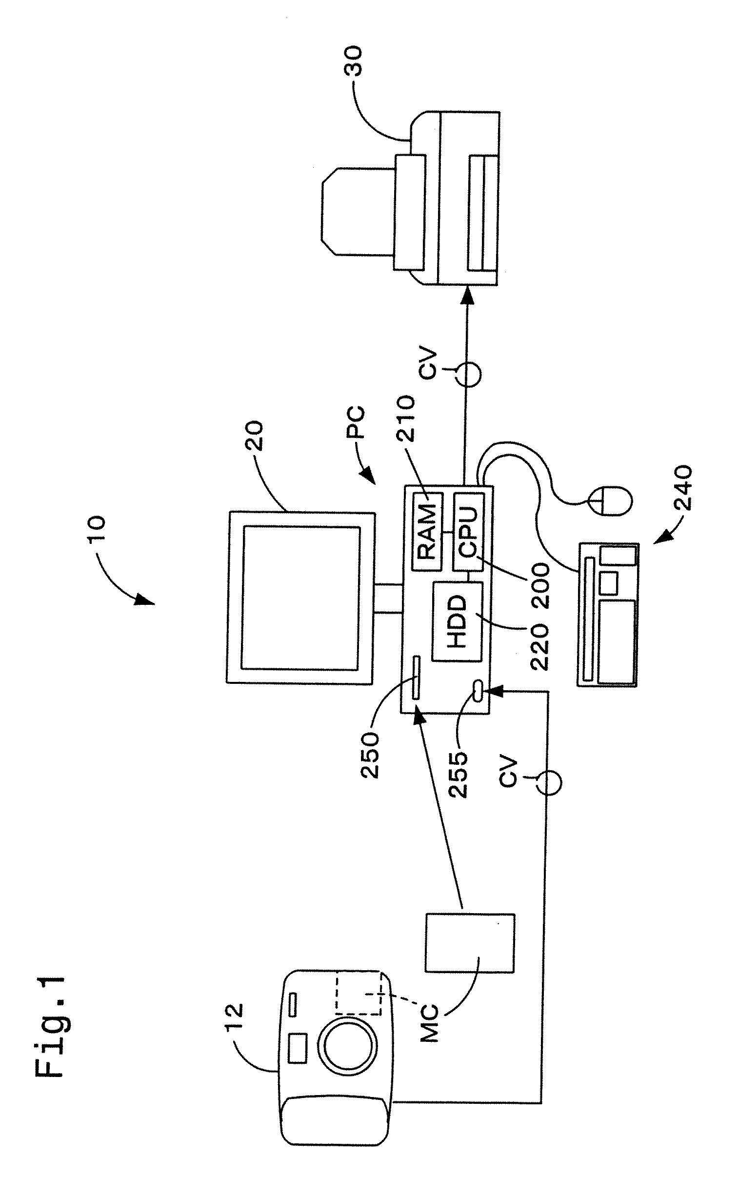
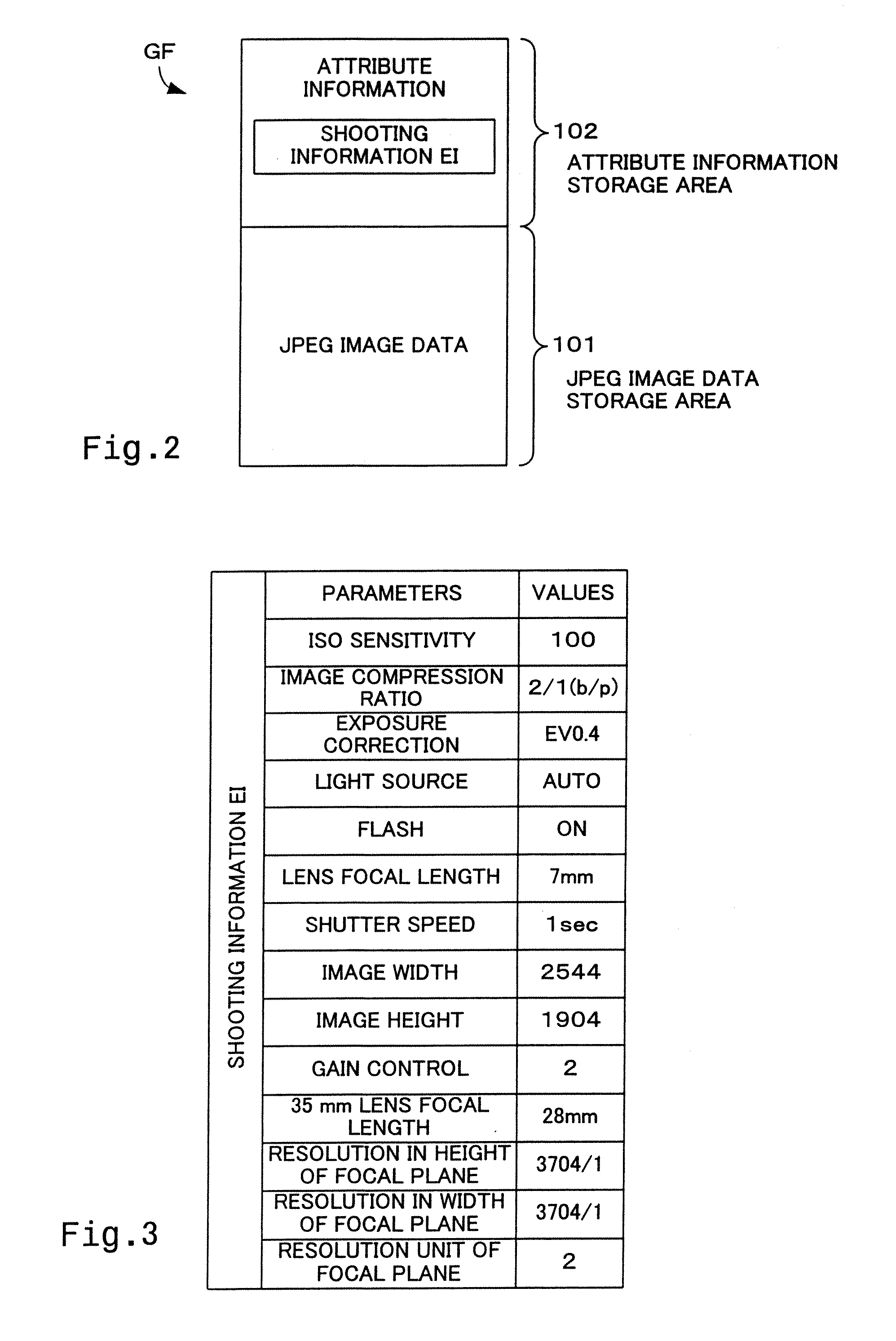
A CPU 200 reads out an image file GF from a memory card MC and stores the read out image file GF temporarily in an RAM 210. The CPU 200 acquires shooting information EI from the read out image file GF and determines the noise reduction level according to the ISO speed. When the ISO speed or the shutter speed exceeds a predetermined value, the CPU 200 increases the noise reduction level and executes noise reduction process.
Description
CROSS-REFERENCE TO RELATED APPLICATIONS[0001]This application is a continuation of U.S. patent application Ser. No. 10 / 486,470, filed on Feb. 9, 2004, which is a national phase entry of PCT / JP02 / 10504, filed on Oct. 9, 2002. The disclosures of these prior applications are hereby incorporated by reference in their entirety for all purposes.TECHNICAL FIELD[0002]The present invention relates to a technique of processing image data with shooting conditions of the image data.BACKGROUND ART[0003]Image data taken (generated) by a digital still camera (DSC) are generally recorded in the form of an image file in conformity with the Exchangeable image file format (Exif), which has been set by Japan EIectronics and Information Technology Industries Association (JEITA), in a recording medium, such as a memory card. The image file in conformity with the Exif format includes image data and Exif information, which is embedded in the image data to describe shooting conditions.[0004]The Exif informa...
Claims
Login to View More Application Information
Patent Timeline
 Patent Type & AuthorityApplications(United States)
IPC IPC(8): H04N5/235H04N5/217H04N5/228H04N5/225H04N1/409G06T5/00H04N1/58H04N5/76H04N5/91
CPCH04N1/409H04N2201/3252H04N5/357H04N1/58H04N25/60
InventorNAKAMI, YOSHIHIROFUJINO, MAKOTO
OwnerNAKAMI YOSHIHIRO