Vehicle light

a technology for vehicles and light sources, applied in the field of vehicles, can solve problems such as deteriorating near-side visibility, and achieve the effects of improving the near-side visibility of drivers, improving long-distance visibility, and increasing the aperture of the lens

Inactive Publication Date: 2011-04-28
STANLEY ELECTRIC CO LTD
View PDF15 Cites 26 Cited by
  • Summary
  • Abstract
  • Description
  • Claims
  • Application Information

AI Technical Summary

Benefits of technology

[0012]According to the other aspect, the upper first refraction surface, the lower first refraction surface, and the lower second refraction surface can be configured so as to project light beams emitted from the light emitting device downward by a larger deflection angle with respect to the horizontal plane as the exit position is farther away from the optical axis in the upper and lower directions. Also, the upper second refraction surface can be configured so as to project the light beams emitted from the light emitting device downward by a larger deflection angle with respect to the horizontal plane as the exit position is farther away from the optical axis in the upper and lower directions. Thereby, the light distribution pattern can be formed so as to extend downward. Accordingly, many remarkable bright-dark boundaries formed between the farther side and the nearer side can be resolved, thereby improving the near-side visibility for a driver.
[0013]Furthermore, the luminous flux can be increased on the travelling side of the road, thereby improving the long-distance visibility.
[0014]According to the still another aspect, since the projection lens can be prevented from being increased in thickness thereof, an increase in the aperture of the lens can be realized. As a result, it is achieved to form a brighter and wider light distribution pattern.
[0015]In the above configuration, the vehicle light can further include a support plate on a front surface of which the light emitting device is mounted, and heat dissipation fins provided to the support plate on a rear surface thereof, and the projection lens can have leg portions that are secured to the support plate. By configuring the light emitting device in such a manner, the generated heat can be effectively dissipated, thereby preventing the uneven light distribution from being formed.
[0016]The vehicle light configured as described above can have the light incident surface formed as a cylindrical concave surface curved horizontally so that a rotation axis of the cylindrical concave surface extends in a vertical direction. This configuration can assist the formation of the desired light distribution pattern more effectively.

Problems solved by technology

However, there is a remarkably clear bright-dark boundary formed between the formed light distribution pattern PA and its adjacent lower area, and the boundary may be erroneously recognized by a driver as a step on a road.
Furthermore, since the technique disclosed in Japanese Patent Application Laid-Open No. 2007-335301 can provide only a limited illumination area in the vertical direction (in the upper and lower directions), the lower area of the light distribution pattern PA is relatively dark, thereby deteriorating the near-side visibility.
In particular, the technique disclosed in Japanese Patent Application Laid-Open No. 2007-335301 may not project light beams on a wider area required for forming a low beam light distribution pattern.

Method used


Image

  • Vehicle light
  • Vehicle light
  • Vehicle light

Examples


first exemplary embodiment

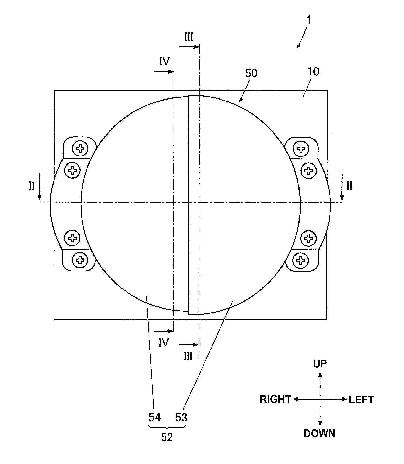
[0046]FIG. 4 is a front view illustrating a direct projection vehicle light according to one exemplary embodiment of the presently disclosed subject matter. FIG. 5 is a cross sectional view of the vehicle light taken along line II-II in FIG. 4. FIG. 6 is a cross sectional view of the vehicle light taken along line III-III in FIG. 4. FIG. 7 is a cross sectional view of the vehicle light taken along line IV-IV in FIG. 4.

[0047]In the illustrated exemplary embodiment, the direct projection vehicle light 1 is used for a low beam vehicle headlamp for left-hand traffic. Accordingly, the right side shall correspond to the opposite side of the road (oncoming car lane) whereas the left side shall correspond to the traveling side road (traveling car lane).

[0048]As shown, the direct projection vehicle light 1 can include a support plate 10, a plurality of heat dissipation fins 20, a lens holder 30, a light emitting device 40, and a projection lens 50, and can have an optical axis Ax.

[0049]The s...

second exemplary embodiment

[0068]FIG. 11 is a front view illustrating a direct projection vehicle light 1A according to another exemplary embodiment of the presently disclosed subject matter. FIG. 12 is a cross sectional view illustrating the vehicle light 1A taken along line IX-IX in FIG. 11. FIG. 13 is a cross sectional view illustrating the vehicle light 1A taken along line X-X in FIG. 11. FIG. 14 is a cross sectional view illustrating the vehicle light taken along line XI-XI in FIG. 11. FIG. 15 is a cross sectional view illustrating the vehicle light taken along line XII-XII in FIG. 11.

[0069]In the illustrated exemplary embodiment, the direct projection vehicle light 1A is used for a low beam vehicle headlamp for the left-hand traffic.

[0070]As shown, the direct projection vehicle light 1A can include a support plate 10A, a plurality of heat dissipation fins 20A, a lens holder 30A, a light emitting device 40A, a projection lens 50A, and can have an optical axis Ax.

[0071]The support plate 10A and the plural...

third exemplary embodiment

[0096]FIG. 21 is a perspective view illustrating a direct projection vehicle light 1B according to still another exemplary embodiment of the presently disclosed subject matter. FIG. 22 is a front view illustrating the direct projection vehicle light 1B. FIG. 23 is a cross sectional view illustrating the vehicle light 1B taken along line XX-XX in FIG. 22. FIG. 24 is a cross sectional view illustrating the vehicle light 1B taken along line XXI-XXI in FIG. 22.

[0097]In the illustrated exemplary embodiment, the direct projection vehicle light 1B is used for a low beam vehicle headlamp for the left-hand traffic.

[0098]As shown, the direct projection vehicle light 1B can include a support plate 10B, a plurality of heat dissipation fins 20B, a lens holder 30B, a light emitting device 40B, and a projection lens 50B.

[0099]The support plate 10B and the plurality of heat dissipation fins 20B can be provided in the same or similar manner as in the first exemplary embodiment.

[0100]The light emitti...


PUM


Abstract

A vehicle light can resolve remarkable bright-dark boundaries formed between a far side and a near side of the light, thereby improving the near-side visibility for a driver. The vehicle light can include a light emitting device having an optical axis and a projection lens. The projection lens can include a light exiting surface that can project light beams emitted by the light emitting device while diffusing the light beams in both left and right directions when observed within a horizontal plane. The light exiting surface can include a left refraction surface that can project the light beams downward by a larger deflection angle with respect to a horizontal plane as the exit position of the light is farther away from the optical axis in the upper and lower directions when observed within a vertical plane. The light exiting surface can also include a right refraction surface that can project the light beams downward by a larger deflection angle with respect to the horizontal plane as the exit position is farther away from the optical axis in the upper and lower directions when observed within a vertical plane.

Description

[0001]This application claims the priority benefit under 35 U.S.C. §119 of Japanese Patent Application No. 2009-243949 filed on Oct. 23, 2009, which is hereby incorporated in its entirety by reference.TECHNICAL FIELD[0002]The presently disclosed subject matter relates to a vehicle light.BACKGROUND ART[0003]Japanese Patent Application Laid-Open No. 2007-335301 (corresponding to U.S. Pat. No. 7,648,262) describes a direct projection type light having a light emitting device 14, a convex lens 12 disposed in front of the light emitting device 14. The convex lens 12 is configured for directly projecting light emitted from the light emitting device 14 forward. The convex lens 12 is also configured to project the light emitted from the light emitting device 14 approximately in parallel with each other when observed within a vertical plane (FIG. 1) while diffusing the light beams when observed within a horizontal plane (FIG. 2). The projected light can form a horizontally wide light distrib...

Claims


Application Information

Patent Timeline
Patent Type & Authority Applications(United States)
IPC IPC(8): F21V5/04B60Q1/04
CPCF21S48/1154F21S48/1258F21V29/763F21S48/328F21V29/004F21S48/1275F21S41/143F21S41/295F21S41/255F21S41/265F21S45/47
Inventor OWADA, RYOTARO
Owner STANLEY ELECTRIC CO LTD
Why Eureka
Try Eureka