Cutting Tool and Cartridge for the Same

a technology of cutting tool and cartridge, which is applied in the field of cutting tools, can solve the problems of interference between the two parts, weakening of the cutter body, and prior art may not provide a sufficient clamping force for the cartridge, and achieves the effect of stable mounting, sufficient fastening force and stable mounting

Active Publication Date: 2011-04-28
TAEGUTEC
View PDF20 Cites 9 Cited by
  • Summary
  • Abstract
  • Description
  • Claims
  • Application Information

AI Technical Summary

Benefits of technology

[0015]According to the present invention, a cartridge, which is adapted to mount cutting inserts, is supported by three surfaces (i.e., a top surface, a bottom surface and a first side surface), thereby allowing a more stable mount and providing sufficient fastening forces when compared to a prior art cartridge using serrations formed on the bottom surface thereof.
[0016]Further, according to the present invention, a cartridge can be stably mounted with only few parts when compared to th...

Problems solved by technology

Such a method, however, requires various metal cutting operations for producing the threaded bores, which may weaken the cutter body.
Further, when the cutting tool is damaged, the part of the screw that breaks off may fall into the threaded bore of the cutter body.
Without such a gap, there may be interference between the two parts, i.e., the cartridge and the body of the cutting tool.
That is, such a structure of the...

Method used


Image

  • Cutting Tool and Cartridge for the Same
  • Cutting Tool and Cartridge for the Same
  • Cutting Tool and Cartridge for the Same

Examples


Embodiment Construction

[0031]The present invention will be hereinafter described in detail with reference to the accompanying drawings.

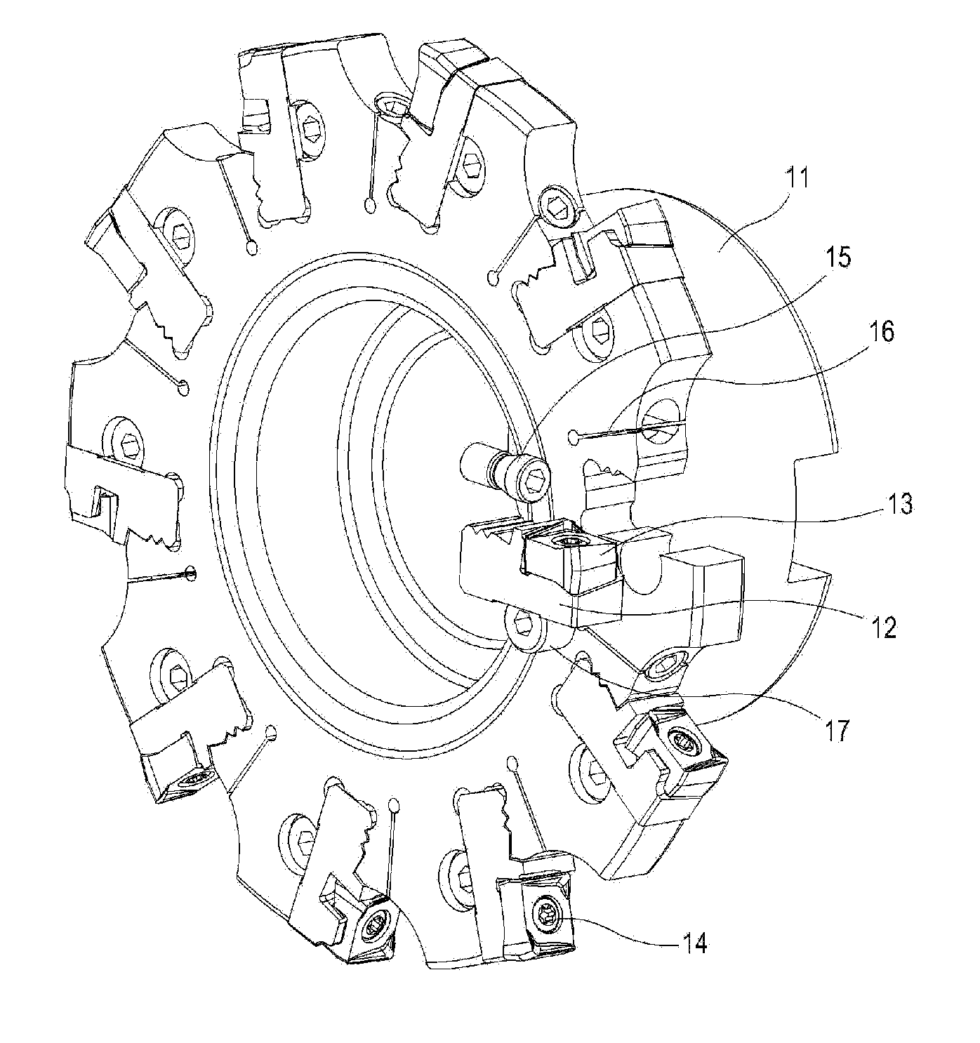
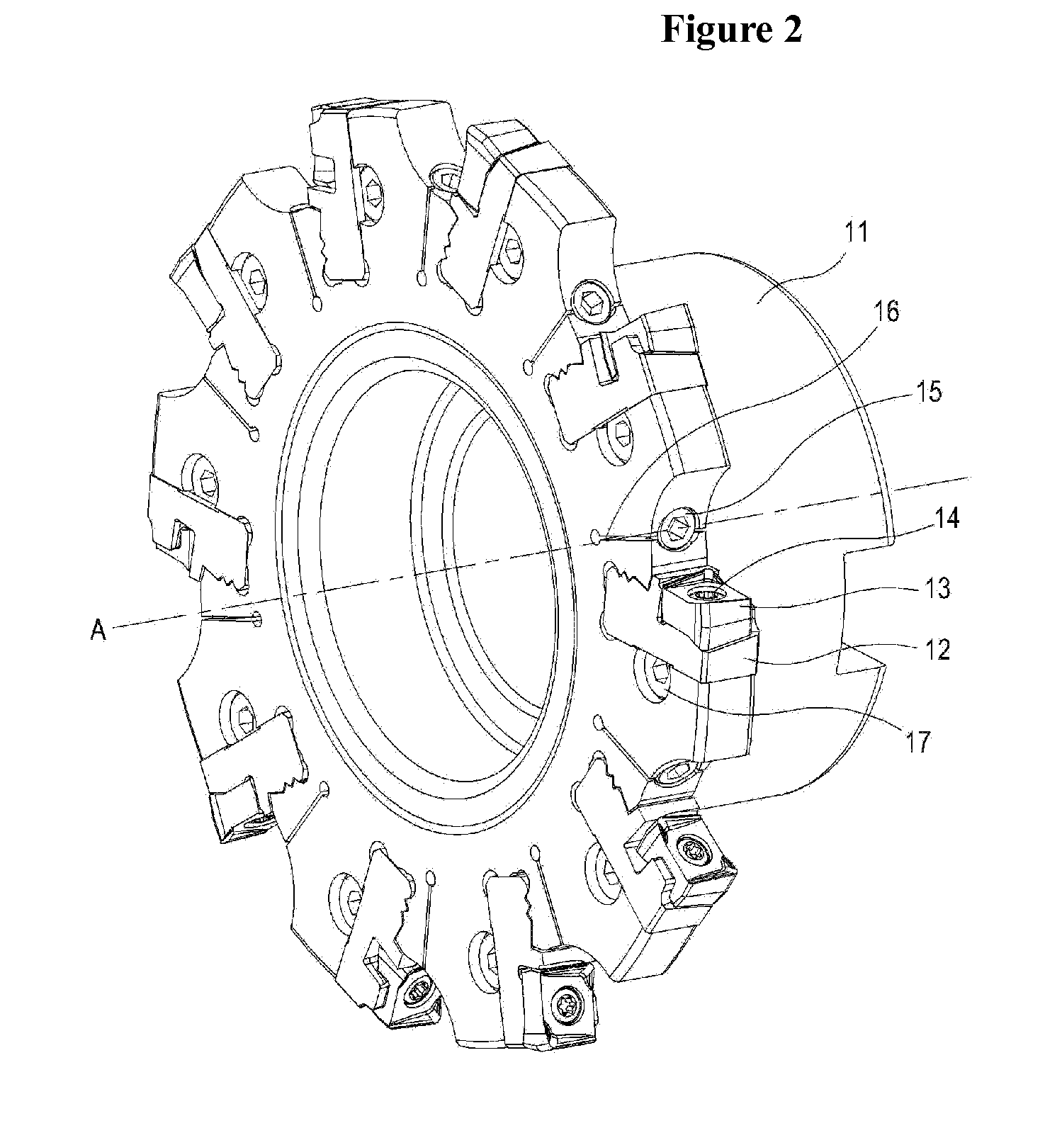
[0032]FIG. 2 is a perspective view of a cutting tool according to an embodiment of the present invention. A plurality of recesses or cartridge pockets for receiving a cartridge 12 are formed on a cutter body 11 along the outer periphery of the cutter body. A cutting insert 13 is fixed on the cartridge 12 by a screw 14. Further, the cartridge 12 is secured to the cutter body 11 by a screw 15. A slot 16 is formed between the screw 15 and the cartridge pocket to facilitate the assembly of the cartridge 12. A screw 17 for adjusting a width of the cutter is inserted between the cutter body and a bottom surface of the cartridge. The cartridge can move in an axial direction A of the cutting tool as the screw 17 rotates. The term “axial direction” of the cutting tool as used herein means a direction denoted by “A” in FIG. 2. Further, the term “radial direction” as used herein mean...


PUM

PropertyMeasurementUnit
Angleaaaaaaaaaa
Angleaaaaaaaaaa
Angleaaaaaaaaaa

Abstract

A cutting tool for machining metallic materials has at least one cutting portion having a cartridge and a cartridge pocket for mounting cutting inserts to the cutting tool. The cartridge pocket has a top surface, a rear supporting surface and a bottom supporting surface. The top surface of the cartridge pocket has one or more serrated projecting portions. The cartridge has an insert pocket, a top surface, a first side surface and a bottom surface. The insert pocket of the cartridge receives a cutting insert. The top surface of the cartridge has one or more outwardly sloped surfaces and one or more inwardly sloped surfaces. The outwardly sloped surfaces mate with the serrated projecting portions. The inwardly sloped surfaces have a gap with respect to the projecting portions of the cartridge pocket.

Description

TECHNICAL FIELD[0001]The present invention relates to a cutting tool for machining metallic materials and a cartridge of a cutting tool for mounting cutting inserts to the cutting tool.BACKGROUND ART[0002]Conventional cutting tools with cartridges, which are adapted to mount cutting inserts, employ various means for securing the cartridges to the cutter body. In some cutting tools, threaded bores are provided in the cutter body and corresponding through bores are provided in the cartridges. The cartridges are secured directly to the cutter body by using screws. Such a method, however, requires various metal cutting operations for producing the threaded bores, which may weaken the cutter body. Further, when the cutting tool is damaged, the part of the screw that breaks off may fall into the threaded bore of the cutter body.[0003]Other conventional cutting tools adopt a structure of securing the cartridge by means of a wedge. Korean Patent Application Laid-Open No. 2005-49530 disclose...

Claims


Application Information

Patent Timeline
IPC IPC(8): B23C5/22B23C5/20B23B27/16
CPCB23C5/2226Y10T407/227B23C2260/80B23C5/08Y10T407/1936Y10T407/1932
Inventor CHOI, CHANG HEEPARK, CHANG GYU
Owner TAEGUTEC
Why Eureka
Try Eureka