Injection mold
a mold and injection technology, applied in the field of injection molds, can solve the problems of poor quality products, precise positioning of inserts in the mold cavity,
- Summary
- Abstract
- Description
- Claims
- Application Information
AI Technical Summary
Problems solved by technology
Method used
Image

Examples
Embodiment Construction
[0012]Embodiments will now be described in detail below, with reference to the drawings.
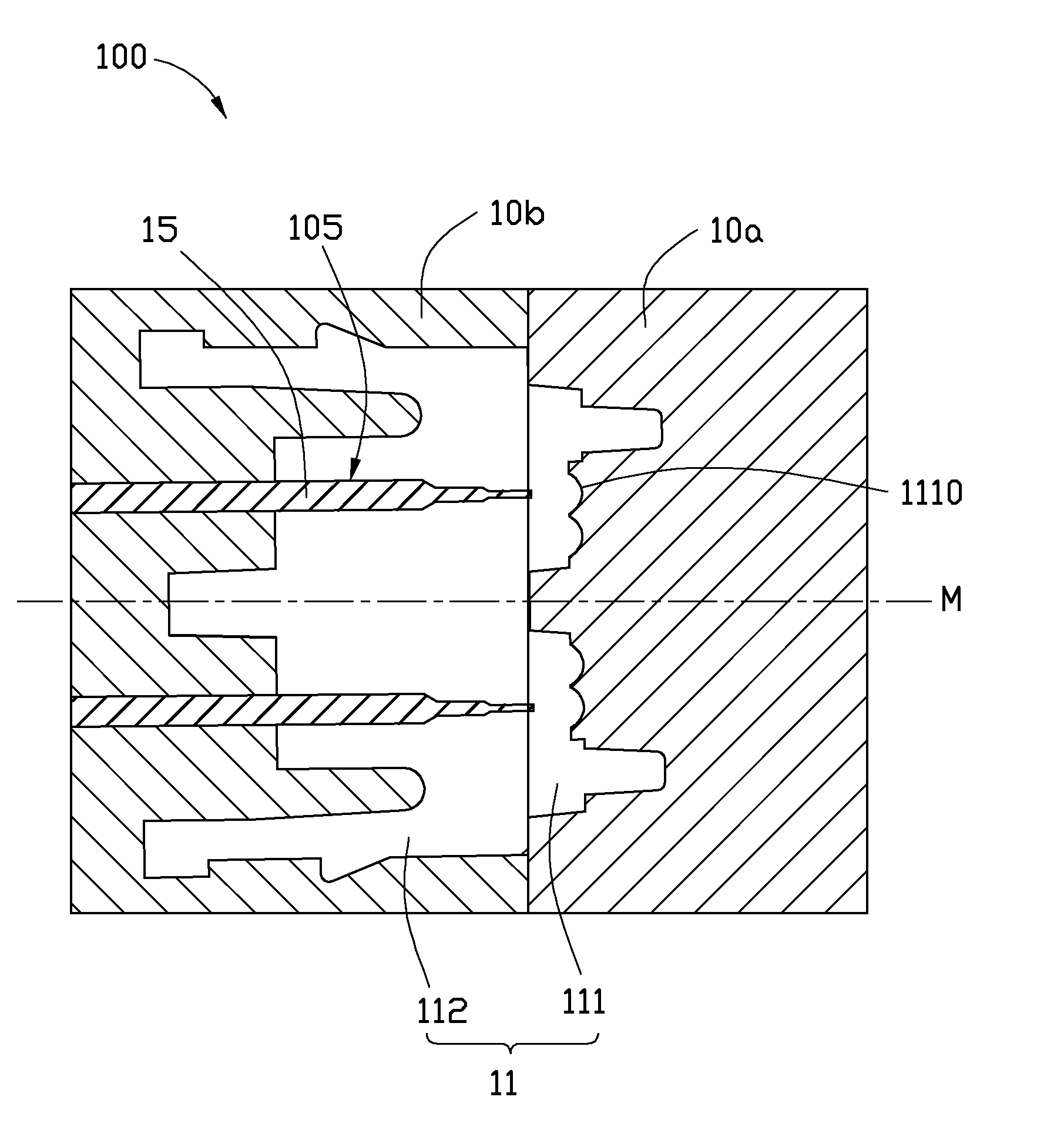
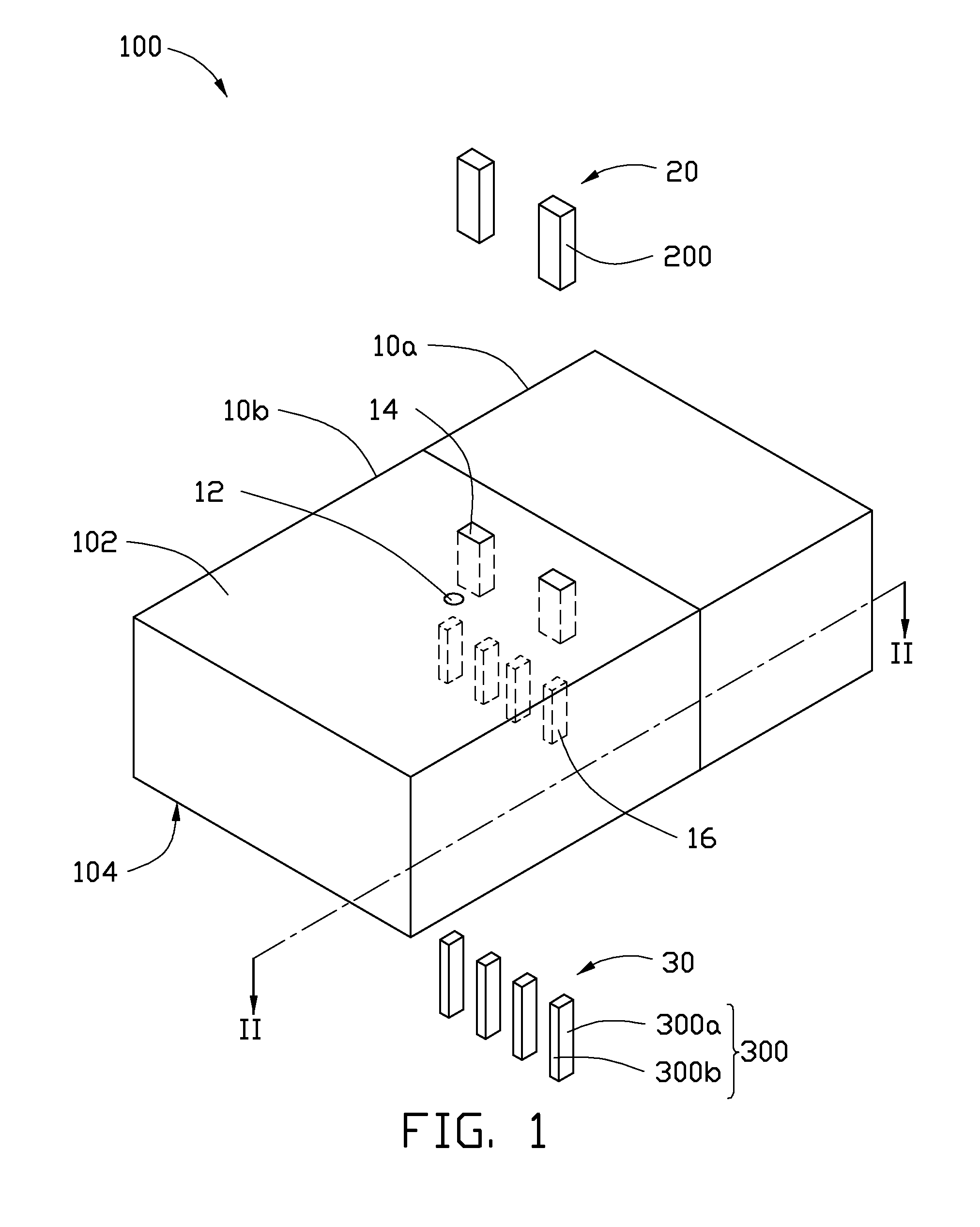
[0013]Referring to FIGS. 1 and 2, an injection mold 100 in accordance with an exemplary embodiment, includes a first mold 10a, a second mold 10b, two inserts 15, two first positioning bars 20, and four second positioning bars 30. The injection mold 100 is configured to manufacture a fiber optic connector 50, as shown in FIGS. 3 and 4. The connector 50 mainly includes a main body 51 and two converging lenses 52 (see FIG. 3). The main body 51 has two receiving holes 514 (see FIG. 4) defined therein for receiving two conventional optical fibers (not shown) respectively. The two converging lenses 52 each align with a corresponding receiving hole 514.
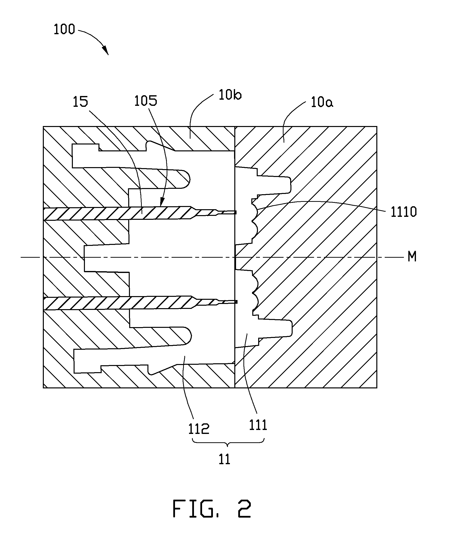
[0014]As shown in FIG. 2, the first mold 10a and the second mold 10b cooperatively define a mold cavity 11. The mold cavity 11 defines a central axis M, and includes a first cavity 111 in the first mold 10a and a second cavity 112 in the second mold 10b. ...
PUM
| Property | Measurement | Unit |
|---|---|---|
| dimension | aaaaa | aaaaa |
| dimensions | aaaaa | aaaaa |
| cylindrical shape | aaaaa | aaaaa |
Abstract
Description
Claims
Application Information
 - Generate Ideas
- Intellectual Property
- Life Sciences
- Materials
- Tech Scout
- Unparalleled Data Quality
- Higher Quality Content
- 60% Fewer Hallucinations
Browse by: Latest US Patents, China's latest patents, Technical Efficacy Thesaurus, Application Domain, Technology Topic, Popular Technical Reports.
© 2025 PatSnap. All rights reserved.Legal|Privacy policy|Modern Slavery Act Transparency Statement|Sitemap|About US| Contact US: help@patsnap.com