Medical instrument

a technology for medical instruments and instruments, applied in the field of medical instruments, can solve problems such as the increase of the scale of the system

Active Publication Date: 2011-04-28
OLYMPUS CORP
View PDF19 Cites 123 Cited by
  • Summary
  • Abstract
  • Description
  • Claims
  • Application Information

AI Technical Summary

Problems solved by technology

However, the method using a magnetic field sensor requires the magnetic field generation coil to ...

Method used


Image

  • Medical instrument
  • Medical instrument
  • Medical instrument

Examples


first embodiment

[0072]Hereinafter, a medical instrument 1 according to a first embodiment of the present invention will be described with reference to the accompanying drawings.

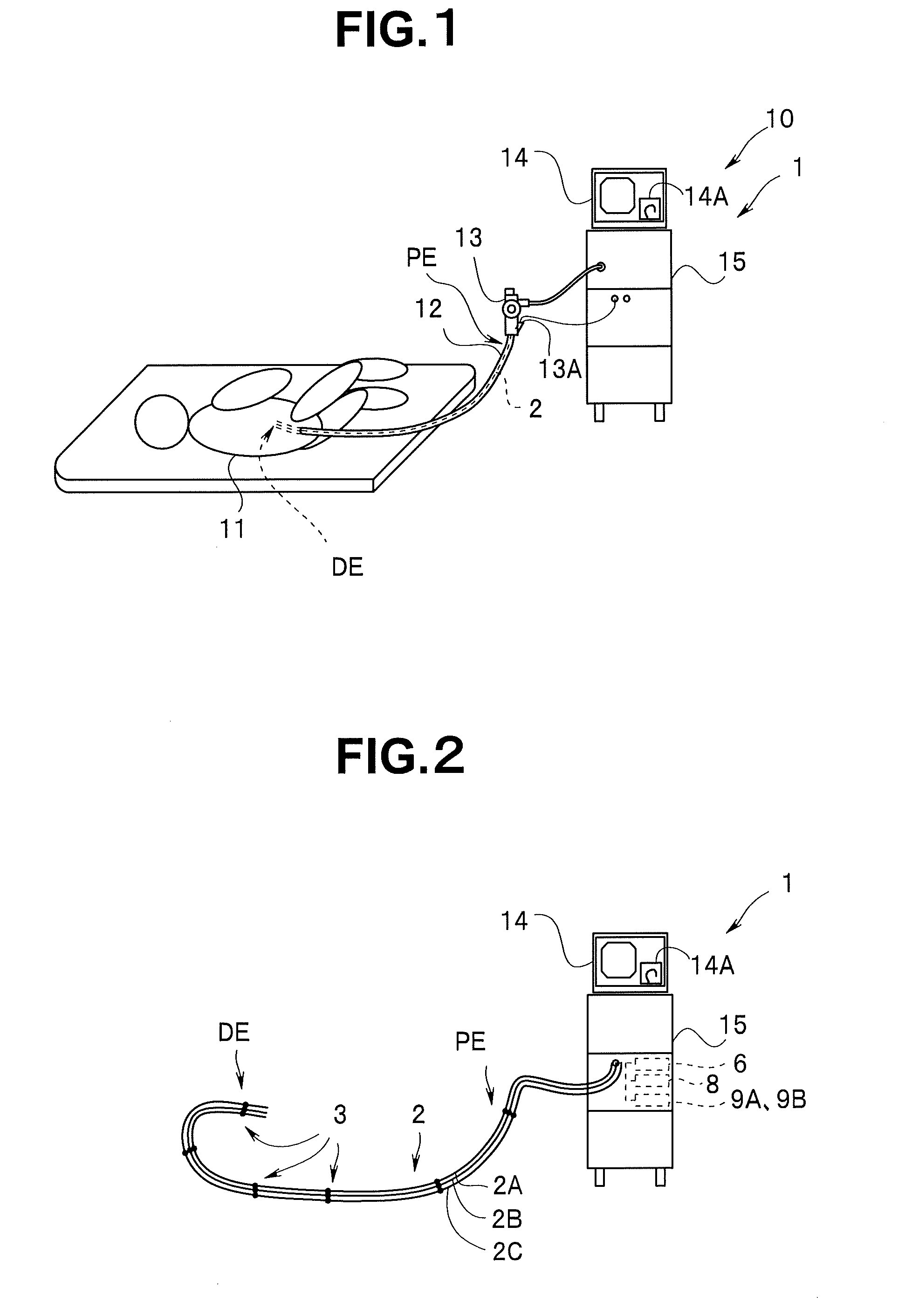
[0073]FIG. 1 is a diagram illustrating a situation in which the medical instrument according to the present embodiment is used and FIG. 2 is a diagram illustrating a configuration of the medical instrument according to the present embodiment.

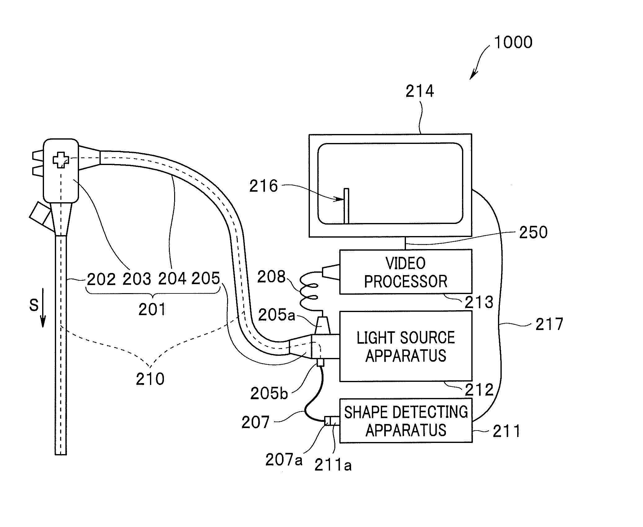
[0074]The medical instrument 1 according to the first embodiment shown in FIG. 1 measures the shape of an insertion portion 12 of an endoscope of an endoscope system 10 using an FBG sensor (see FIG. 2). The endoscope system 10 includes the insertion portion 12 of the endoscope which is a medical appliance inserted in the interior of an examinee 11 who is an object to be examined, for performing an observation or treatment and is an elongated insertion body, an operation portion 13 for operating the insertion portion 12, a main unit 15 that performs control over the entire endoscope syste...

second embodiment

[0130]Hereinafter, a medical instrument 1B according to a second embodiment of the present invention will be described with reference to the accompanying drawings. Since the configuration and operation of the medical instrument 1B are similar to those of the medical instrument 1 of the first embodiment, the same components will be assigned the same reference numerals and descriptions thereof will be omitted.

[0131]FIG. 16 is a structural diagram illustrating a structure of a cross section of a distal end portion DE of an insertion portion of the medical instrument according to the second embodiment, and FIG. 17 and FIG. 18 are diagrams illustrating processing by the calculation section of the medical instrument 1 of the second embodiment.

[0132]As shown in FIG. 16, in the medical instrument 1B of the present embodiment, a gravity sensor 16, which is gravity detecting means, is disposed at a distal end portion DE of the insertion portion 12. A CCD 12B which is image pickup means and a ...

third embodiment

[0136]FIG. 19 is a diagram illustrating a situation in which a medical instrument according to the present embodiment is used and FIG. 20 is a diagram illustrating a configuration of the medical instrument according to the present embodiment.

[0137]The configuration of the medical instrument according to the third embodiment is different from the medical instrument of the first embodiment shown in aforementioned FIG. 1 to FIG. 15 and the medical instrument according to the second embodiment shown in FIG. 16 to FIG. 18 in that the operation portion is provided with a gyroscope and an acceleration sensor. Therefore, only the differences will be described and the same components as those in the first embodiment will be assigned the same reference numerals and descriptions thereof will be omitted.

[0138]In the medical instrument 1C of the third embodiment shown in FIG. 19, the operation portion 13 is provided with a gyroscope 21 and an acceleration sensor 22 which are movement sensors for...


PUM


Abstract

A medical instrument including a distortion detection probe disposed in an insertion portion to be inserted into the interior of an examinee provided with a plurality of FBG sensor sections that detect distortion of the insertion portion, a coordinate calculation section that calculates first three-dimensional coordinates of the respective FBG sensor sections according to a first three-dimensional coordinate system whose origin is a predetermined position based on the detection results of the FBG sensor sections, a coordinate system setting section that sets a second three-dimensional coordinate system based on the first three-dimensional coordinates of the respective FBG sensor sections, a coordinate transformation section that transforms the first three-dimensional coordinates of the respective FBG sensor sections into second three-dimensional coordinates according to the second three-dimensional coordinate system set by the coordinate system setting section and a shape display section that displays the shape of the insertion portion based on the second three-dimensional coordinates transformed by the coordinate transformation section.

Description

CROSS REFERENCE TO RELATED APPLICATION[0001]This application is a continuation application of PCT / JP2009 / 068529 filed on Oct. 28, 2009 and claims benefit of Japanese Applications No. 2008-277086 filed in Japan on Oct. 28, 2008, No. 2008-277087 filed in Japan on Oct. 28, 2008, No. 2008-277089 filed in Japan on Oct. 28, 2008, No. 2008-277090 filed in Japan on Oct. 28, 2008, No. 2008-277091 filed in Japan on Oct. 28, 2008, the entire contents of each of which are incorporated herein by their reference.BACKGROUND OF THE INVENTION[0002]1. Field of the Invention[0003]The present invention relates to a medical instrument provided with an insertion body to be inserted into the interior of an object to be examined.[0004]2. Description of the Related Art[0005]As a method of calculating a shape of an insertion portion of an endoscope or the like to be inserted into the interior of an examinee, one using a magnetic field sensor as described in Japanese Patent Application Laid-Open Publication N...

Claims


Application Information

Patent Timeline
IPC IPC(8): A61B1/00A61B1/07
CPCA61B1/0051A61B1/31G02B23/2476A61B5/065A61B2019/5261A61B5/06A61B2034/2061A61B1/009
Inventor ONODA, FUMIYUKIUSHIFUSA, HIROYUKIODA, TOMOHIKOHASEGAWA, JUNFUKUCHI, MASAMIHIRAKAWA, KATSUMI
Owner OLYMPUS CORP
Why Eureka
Try Eureka