Bragg grating and method of producing a Bragg grating using an ultrafast laser

Active Publication Date: 2006-04-18
NAT RES COUNCIL OF CANADA
View PDF31 Cites 63 Cited by
  • Summary
  • Abstract
  • Description
  • Claims
  • Application Information

AI Technical Summary

Benefits of technology

[0034]disposing and orienting a mask adjacent to the at least partially transmissive material at a distance “d” such that group velocity walk-off results in pure 2-beam interference within the at least partially transmissive material when irradiated with a pulse of light of less than or equal to 100 picoseconds, wherein the distance “d” is chosen such that the difference in times of arrival of the order pairs due to group velocity walk-off results in-the pure 2-beam interference pattern of subbeams of said pulse of light

Problems solved by technology

These prior art gratings provide a useful function, however they are known to suffer from some limitations in terms of the out-of-band loss that results from coupling of the fundamental core mode LP01 into backward-propagating lossy cladding modes.
Power that is coupled into the cladding modes is not entirely guided hence it is lost through absorption or scattering through the fiber coating.
These prior art fiber designs provide a useful function however they suffer from some limitations.
Often the complicated fiber chemistry results in a fiber that possesses many internal stresses, which makes the fiber more fragile.
Mode field

Method used


Image

  • Bragg grating and method of producing a Bragg grating using an ultrafast laser
  • Bragg grating and method of producing a Bragg grating using an ultrafast laser
  • Bragg grating and method of producing a Bragg grating using an ultrafast laser

Examples


Embodiment Construction

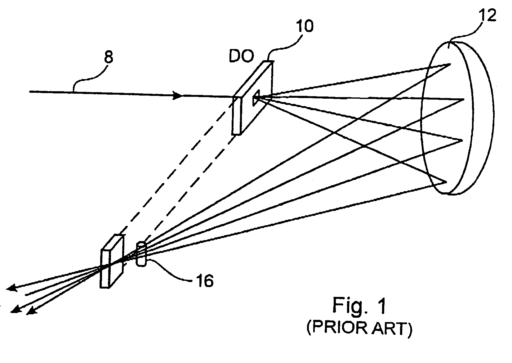
[0060]Referring to FIG. 1, the prior art of Miller et al. is shown. A femtosecond laser pulse 8 is incident on a diffractive element 10. The laser pulse 8 is diffracted and propagates to a curved mirror 12. The laser pulse is reflected and propagates into a lens 16. The laser pulse then propagates from the lens to the target.

[0061]Unfortunately, the technique taught by Miller et al. is very sensitive to the alignment of the various optical components. This technique is an interferometric technique, which incorporates a diffractive optic to split a beam to produce a plurality of beams. The optical path lengths of the diffracted beams should be the same length within a tolerance corresponding to the physical presence of the electromagnetic radiation i.e. approximately 30 μm for 125 femtosecond laser pulses. Although not impossible, it is often difficult to provide such highly accurate path lengths, even with costly equipment. Consequently, when such a technique is used to produce a Br...


PUM


Abstract

A novel Bragg grating filter in optical waveguiding fiber with suppressed cladding mode coupling and method of producing same is disclosed. The novel grating structure is induced in both the core and the cladding of the optical fiber irrespective of the photosensitivity of the core or cladding to actinic radiation. Such core and cladding of the optical fiber need not be chemically doped to support the grating. The method incorporates an ultra short duration pulse laser source. Electromagnetic radiation provided from the laser propagates to a diffractive element positioned a specific distance to the target material such that the diffracted electromagnetic radiation forms a 2-beam interference pattern, the peaks of which are sufficiently intense to cause a change in index of refraction.

Description

CROSS-REFERENCE TO RELATED APPLICATIONS[0001]This application is a continuation-in-part of U.S. patent application Ser. No. 10 / 639,486 filed Aug. 13, 2003, which claims priority from U.S. provisional Application 60 / 456,184 filed Mar. 21, 2003. This application also claims priority from U.S. Provisional Application No. 60 / 545,949 filed Feb. 20, 2004, Canadian application 2,436,499 filed Aug. 1, 2003, and European Application 03405845.3 filed Nov. 26, 2003, which are all incorporated herein by reference.FIELD OF THE INVENTION[0002]This invention relates generally to the direct writing of gratings in light transmissive or light absorbing optical media such as optical fiber and waveguides using a diffraction grating and femtosecond pulsed light; and, one aspect of this invention relates to a method of suppression of cladding modes in optical fiber or waveguides with gratings therein.BACKGROUND OF THE INVENTION[0003]The fabrication of many photonic devices has been achieved through expos...

Claims


Application Information

Patent Timeline
IPC IPC(8): G02B6/34G02B5/18G02B6/02G02B6/124
CPCG02B5/1857G02B6/124G02B6/02138G02B6/021
Inventor MIHAILOV, STEPHEN J.GROBNIC, DANSMELSER, CHRISTOPHERWALKER, ROBERTLU, PINGDING, HUIMINHENDERSON, GEORGEDAI, XIAOLI
Owner NAT RES COUNCIL OF CANADA
Why Eureka
Try Eureka