Triaxial fiber optic force sensing catheter

a fiber optic and force sensing technology, applied in the direction of force measurement by measuring optical property variation, force/torque/work measurement apparatus, instruments, etc., can solve the problems of time-consuming, manual feedback, complicated mapping procedure, etc., to improve the sensitivity of force resolution and reduce the profile over existing devices

Active Publication Date: 2013-10-29
ST JUDE MEDICAL INT HLDG SARL
View PDF174 Cites 62 Cited by
  • Summary
  • Abstract
  • Description
  • Claims
  • Application Information

AI Technical Summary

Benefits of technology

[0019]Various embodiments of the invention include a structural member that improves the sensitivity of the force resolution over existing fiber optic strain sensing catheters by up to an order of magnitude. Some embodiments are further characterized as having a reduced profile over existing devices.
[0020]Structurally, the flexures of the various embodiments of the present invention include a cross-section having a stiffness (area moment of inertia) about a first axis that is on the order of 20 times less than the stiffness of a second axis that is orthogonal to the first axis. The relatively small stiffness about the first axis causes the flexure to bend preferentially due to moments about the first axis while bending about the second, orthogonal axis is minimal, thereby transferring the torsional forces about the second orthogonal axis onto other portions of the structural member. In this way, the flexures enable isolation of moments and moment forces about the first axis.

Problems solved by technology

Often, the mapping procedure is complicated by difficulties in locating the zone(s) to be treated due to periodic movement of the heart throughout the cardiac cycle.
One drawback of such previously known mapping systems is that they rely on manual feedback of the catheter and / or impedance measurements to determine when the catheter is properly positioned in the vessel or organ.
Those systems do not measure contact forces with the vessel or organ wall or detect contact forces applied by the catheter against the organ or vessel wall that may modify the true wall location.
Instead, previously known mapping methods are time-consuming, dependent upon the skill of the clinician, and cannot compensate for artifacts created by excessive contact forces.
Such arrangements, however, may be inherently imprecise due to the motion of the organ or vessel.
Moreover, the previously-known systems do not provide the ability to sense the load applied to the distal extremity of the catheter by movement of the tissue wall.
For example, in the case of a cardiac ablation system, at one extreme the creation of a gap between the end effector of the treatment system and the tissue wall may render the treatment ineffective, and inadequately ablate the tissue zone.
At the other extreme, if the end effector of the catheter contacts the tissue wall with excessive force, it may inadvertently puncture the tissue, resulting in cardiac tamponade.
One drawback of such devices, however, is that they are relatively complex and must be sealed to prevent blood or other liquids from disturbing the measurements.
In addition, such load sensing devices may result in an increase in the insertion profile of the distal extremity of the catheter.
Still further, sensors of the types described in that patent may be subject to electromagnetic interference.
Existing fiber optic strain sensing catheters are typically limited to resolving forces to within approximately ±1-gm of force.
In addition, the tri-axial force sensors tend to involve complex machining and fabrication to achieve the desired isolation effect.

Method used


Image

  • Triaxial fiber optic force sensing catheter
  • Triaxial fiber optic force sensing catheter
  • Triaxial fiber optic force sensing catheter

Examples


Embodiment Construction

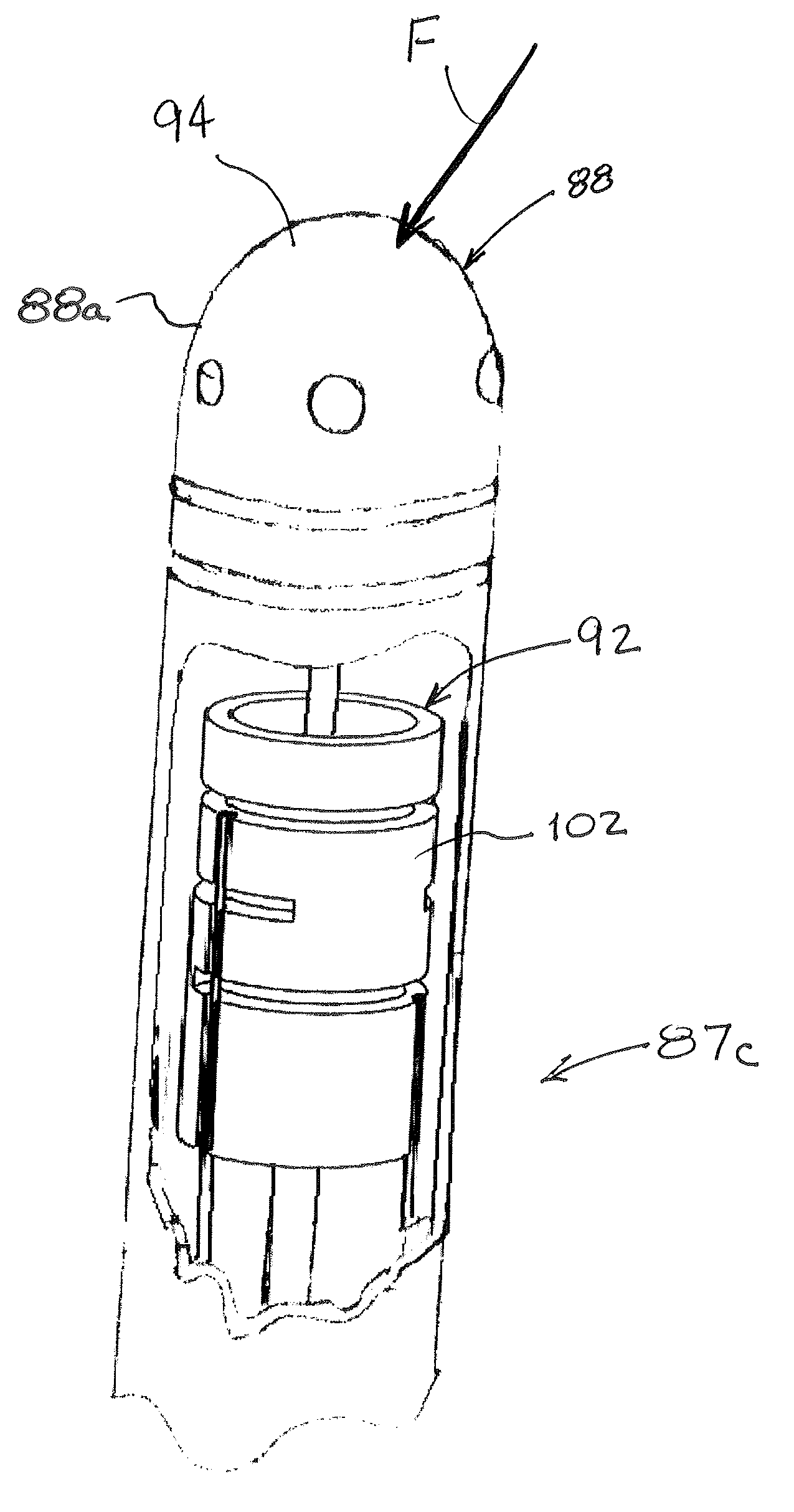
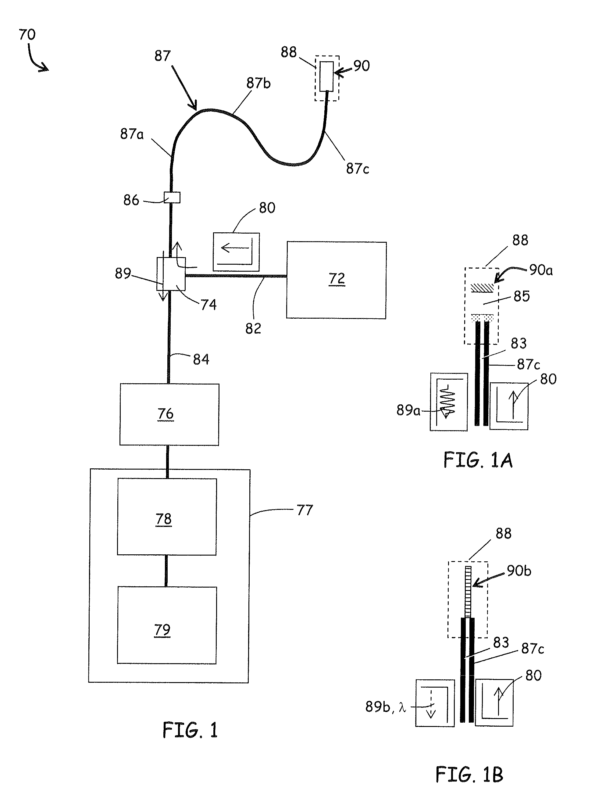
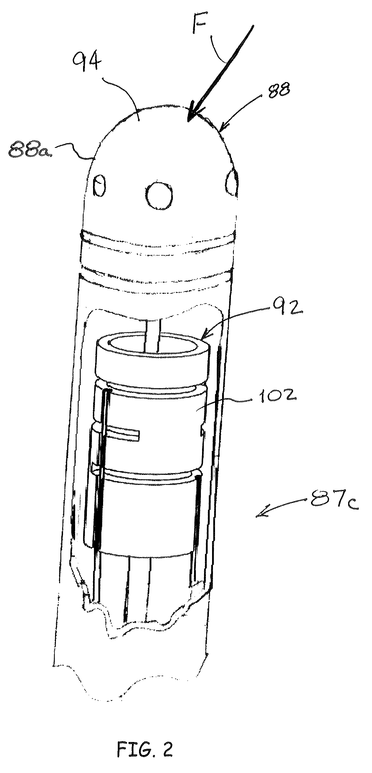
[0043]Referring to FIG. 1, an embodiment of a strain sensing system 70 is depicted in accordance with the invention. The strain sensing system 70 may comprise an electromagnetic source 72, a coupler 74, a receiver 76, an operator console 77 operatively coupled with a microprocessor 78 and a storage device 79. The electromagnetic source 72 outputs a transmitted radiation 80 of electromagnetic radiation that is substantially steady state in nature, such as a laser or a broadband light source. A transmission line 82 such as a fiber optic cable carries the transmitted radiation 80 to the coupler 74, which directs the transmitted radiation 80 through a transmitting / receiving line 84 and through a fiber optic element 83 (FIG. 1A) contained within a flexible, elongate catheter assembly 87 to a fiber optic strain sensing element 90. The fiber optic element 83 of the catheter assembly 87 and transmitting / receiving line 84 may be coupled through a connector 86 as depicted in FIG. 1.

[0044]The ...


PUM

PropertyMeasurementUnit
flexibleaaaaaaaaaa
distanceaaaaaaaaaa
areaaaaaaaaaaa

Abstract

A fiber optic force sensing assembly for detecting forces imparted at a distal end of a catheter assembly. The structural member may include segments adjacent each other in a serial arrangement, with gaps located between adjacent segments that are bridged by flexures. Fiber optics are coupled to the structural member. In one embodiment, each fiber optic has a distal end disposed adjacent one of the gaps and oriented for emission of light onto and for collection of light reflected from a segment adjacent the gap. The optical fibers cooperate with the deformable structure to provide a change in the intensity of the reflected light, or alternatively to provide a variable gap interferometer for sensing deformation of the structural member. In another embodiment, the gaps are bridged by fiber Bragg gratings that reflect light back through the fiber optic at central wavelengths that vary with the strain imposed on the grating.

Description

RELATED APPLICATIONS[0001]This application is a continuation-in-part of and claims priority to U.S. patent application Ser. No. 11 / 450,072, filed Jun. 9, 2006, which is hereby incorporated by reference herein its entirety. This application further claims benefit of the filing date of U.S. Provisional Patent Application No. 61 / 143,718, filed Jan. 9, 2009, which is hereby incorporated by reference herein in its entirety.FIELD OF THE INVENTION[0002]The disclosed invention relates generally to force sensing devices capable of resolving the magnitude and direction of a force vector. More specifically, the invention relates to a force sensing tip to aid in the positioning of catheters used in humans or animals, or for serving as feedback elements in robotic surgical systems.BACKGROUND[0003]For many years, exploration and treatment of various organs or vessels has been possible using catheter-based diagnostic and treatment systems. Such catheters are introduced through a vessel leading to ...

Claims


Application Information

Patent Timeline
Patent Type & Authority Patents(United States)
IPC IPC(8): G01L1/24
CPCA61B5/0084A61B5/0422A61B5/6849A61B5/6885A61B17/320758G01L5/166A61B19/46A61B18/1492A61B18/02A61B2019/464A61B2019/465A61B2562/02A61B2562/0266A61B2090/064A61B90/06A61B2090/065A61B5/287A61B1/00097A61B1/00A61B1/00096A61B1/07A61M25/00A61M25/0054A61M25/0067A61M25/0074A61M25/0082
Inventor AEBY, NICOLASLEO, GIOVANNI
Owner ST JUDE MEDICAL INT HLDG SARL
Why Eureka
Try Eureka