Linear transport device

a transportation device and linear technology, applied in transportation and packaging, electric vehicles, vehicle components, etc., can solve the problems of difficult to pull away the platform car and remove it from the rail in an assembled state, and achieve the effect of reducing the magnetic suction for

Active Publication Date: 2011-05-05
YAMAHA MOTOR CO LTD
View PDF4 Cites 40 Cited by
  • Summary
  • Abstract
  • Description
  • Claims
  • Application Information

AI Technical Summary

Benefits of technology

[0009]The present invention is provided with a rail fixed to a base, a platform car movably supported on the rail, and a linear motor that drives the platform car. The linear motor includes a stator disposed on the base and a mover disposed on the platform car so as to face the stator. One of the stator and the mover is a permanent magnet, and the other is an electromagnet with a coil. The platform car of the present invention is detachable from the rail in an opposing direction along which the platform car faces a surface of the base to which the rail is fixed. Nevertheless, since the stator of the base and the mover of the movable assembly are magnetically pulling to each other even in a state where the supply of alternating current is suspended, it is difficult to pull away the platform car and remove it from the rail in an assembled state. As a result of intense study, the present inventors resolved the foregoing problem by providing a mechanism for reducing the magnetic suction force working between the stator and the mover in a state of not energizing the coil, and thereby completed this invention.

Problems solved by technology

Nevertheless, since the stator of the base and the mover of the movable assembly are magnetically pulling to each other even in a state where the supply of alternating current is suspended, it is difficult to pull away the platform car and remove it from the rail in an assembled state.

Method used


Image

  • Linear transport device
  • Linear transport device
  • Linear transport device

Examples


first embodiment

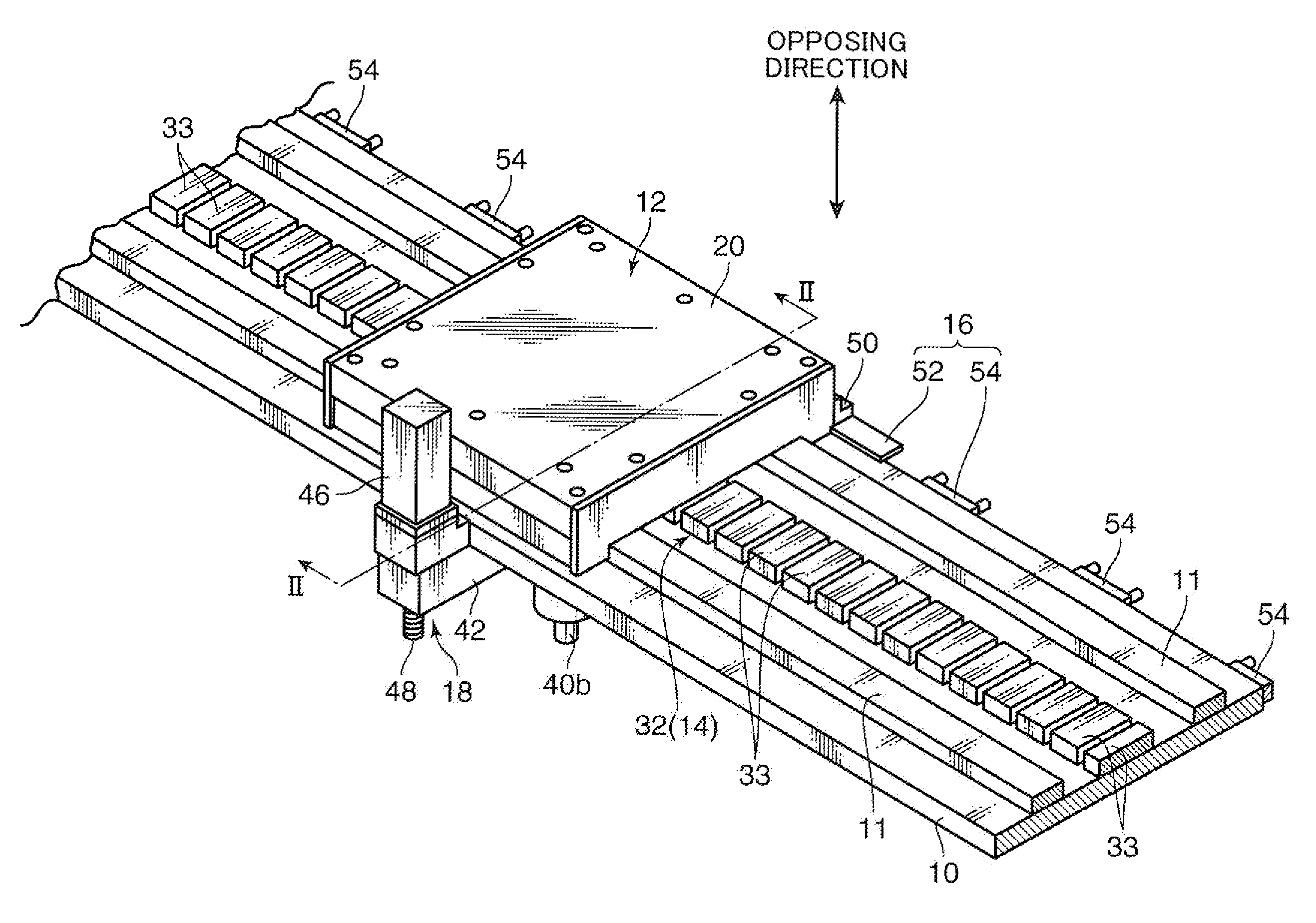
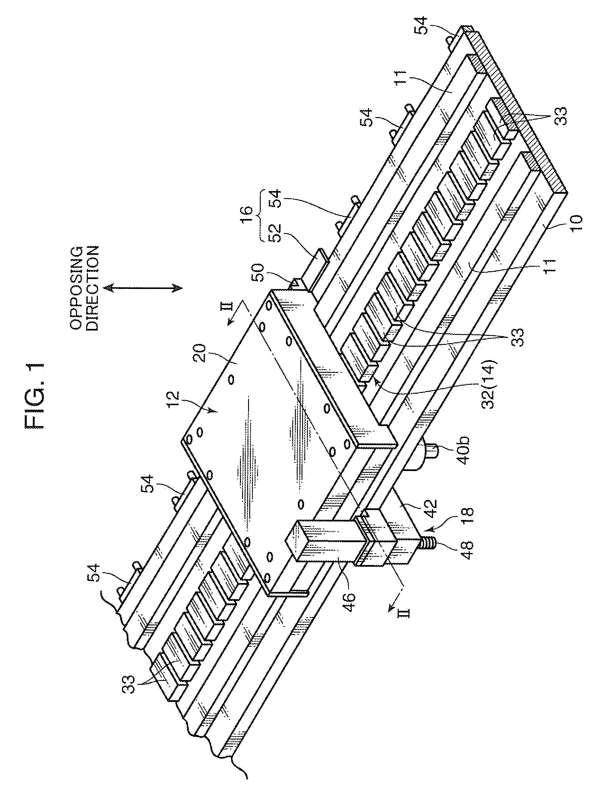
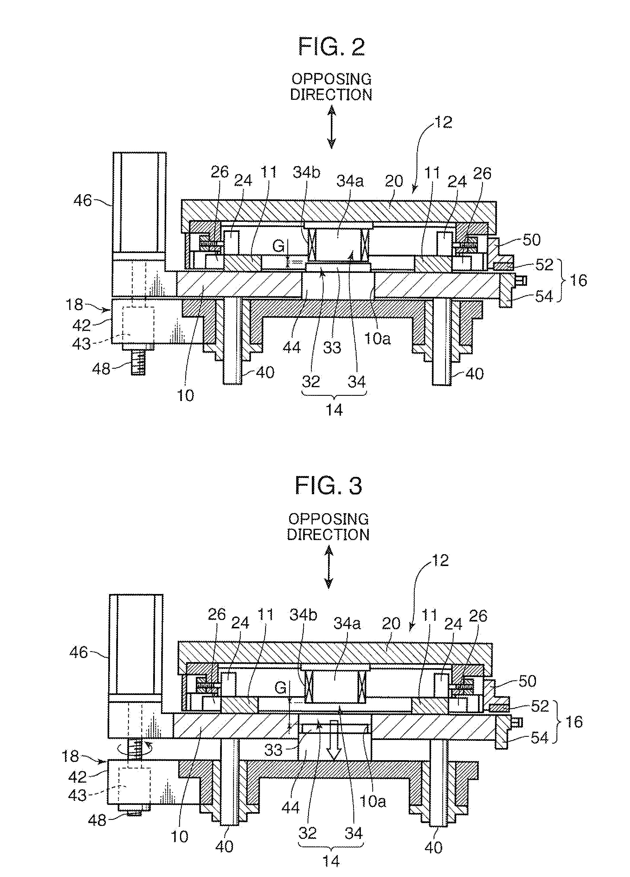
[0020]FIGS. 1 and 2 show the linear transport device according to the present invention, wherein FIG. 1 is a perspective view showing the linear transport device and FIG. 2 is a longitudinal cross section (cross section of line II-II of FIG. 1) of the linear transport device, respectively. As shown in these Figures, the linear transport device includes a base 10 that is disposed horizontally, a pair of linear rails 11 fixed on the base and extending in alignment in a mutually parallel manner, a platform car 12 which is movably supported on the rails 11, a linear motor 14 for driving the platform car 12, a position detection device 16 of the platform car 12, and a gap variable mechanism 18.

[0021]Each of the rails 11 has a square cross section, which is, for example, a rectangular cross section.

[0022]Referring to FIG. 2, the platform car 12 is provided with a rectangular platform body 20 in a planar view.

[0023]The platform body 20 is provided with a plurality of first guide rollers 24...

second embodiment

[0042]The linear transport device according to the present invention is now explained.

[0043]FIGS. 4 and 5 show the linear transport device according to the second embodiment, wherein FIG. 4 is a perspective view showing the linear transport device, and FIG. 5 is a side view (arrow view in the V direction of FIG. 4), respectively.

[0044]The linear transport device according to the second embodiment differs from the configuration of the first embodiment in that it is provided with a manual gap variable mechanism 18 that is explained below in substitute for the motor-driven gap variable mechanism 18 explained in the first embodiment. Since the remainder of the configuration is basically the same as the first embodiment, the ensuing explanation will mainly refer to the configuration of the gap variable mechanism 18 as the point of difference.

[0045]The gap variable mechanism 18 according to the second embodiment is configured, as shown in FIG. 4 and FIG. 5, to lift up the platform car 12 ...

third embodiment

[0056]The linear transport device according to the present invention is now explained.

[0057]FIG. 7 shows a longitudinal cross section of the linear transport device according to the third embodiment. The linear transport device of the third embodiment shown in FIG. 7 differs from the configuration of the first embodiment with respect to the following points, and the remaining configuration is basically common with the linear transport device of the first embodiment.

[0058]Foremost, the structure shown in FIG. 6 is applied as the support structure of the platform car 12 relative to the rails 11. Moreover, a permanent magnet-based linear motor is applied as the linear motor 14, and the opposite surfaces of the stator 32 and the mover 34 of the linear motor 14 are vertical. That is, the stator 32 and the mover 34 face each other in the horizontal direction. As explained below, the gap variable mechanism 18 is configured to elongate the gap G between the stator 32 and the mover 34 by mov...


PUM


Abstract

Disclosed is a linear transport device. A platform car of the linear transport device is detachably mounted on a rail fixed to a base in an opposing direction along which the platform car faces the mounting surface of the base. A linear motor that drives the platform car is provided. The linear motor includes a stator disposed on the base and a mover disposed on the platform car so as to face the stator. One of the stator and the mover is a permanent magnet, and the other is an electromagnet. A relative position variable mechanism for relatively displacing the stator and the mover so as to reduce the magnetic suction force generated between the stator and the mover is provided.

Description

BACKGROUND OF THE INVENTION[0001]1. Field of the Invention[0002]The present invention relates to a linear transport device which uses a linear motor as its drive source.[0003]2. Description of the Related Art[0004]A linear transport device of this type is provided with a base, rails that are laid on the base, and a platform car that moves on and along the rails. In order to drive the platform car, a linear motor has been conventionally used as the drive source. A well-known linear motor is provided with a stator fixed to the foregoing base, and a mover fixed to the platform car. With respect to the stator and the mover, one is a permanent magnet and the other is an electromagnet. By controlling current supply to the coil of the electromagnet, the propulsion is generated to the platform car based on the mutual effect of the magnetic flux between the stator and the mover.[0005]The platform car is configured such that it is mounted on the rails and is only allowed to move in the longit...

Claims


Application Information

Patent Timeline
Patent Type & Authority Applications(United States)
IPC IPC(8): B60L13/03
CPCB60L13/03B60L2200/26B60L13/06B65G54/02H02K41/031H02K2213/09H02K21/026
Inventor FUKUKAWA, YOSHIAKI
Owner YAMAHA MOTOR CO LTD
Why Eureka
Try Eureka