Limb supporting apparatus

a technology for supporting devices and limbs, applied in the field of arm protection devices, can solve problems such as pain, swelling, blistering, and inability to control the position of limbs, and achieve the effect of reducing the likelihood of pressure injury

Inactive Publication Date: 2011-05-05
SILFVERSKIOLD KRIS
View PDF12 Cites 7 Cited by
  • Summary
  • Abstract
  • Description
  • Claims
  • Application Information

AI Technical Summary

Benefits of technology

[0009]According to a first aspect of the invention, there is provided an arm protection apparatus for protecting an arm, the apparatus including: a channel formed from a pliant material and defining an upwardly opening mouth for receiving the arm, the channel having an upper arm receiving portion and a lower arm receiving portion; an upper arm strap having a first end connected to a first side of the upper arm receiving portion and a second end adapted for releasable engagement with a second side of the upper arm receiving portion; a lower arm strap having a first end connected to a first side of the lower arm receiving portion and a second end adapted for releasable engagement with a second side of the lower arm receiving portion, wherein, in use, the channel and the straps encircle the arm and the apparatus distributes pressure on immobilized tissue of the arm so as to reduce the likelihood of pressure injury. In one form the upper and lower arm receiving portions are partially separated by an upwardly opening lateral slot. In one form the apparatus includes a means for attaching the channel to an arm board of an operating table.

Problems solved by technology

However, under anaesthetic or during emergency transport, patients have little or no control over the position of their limbs and thus rely on correct placement of such limbs by attending medical professionals.
Such damage may include injury due to excessive pressure on immobilized tissue.
Excessive pressure in an anaesthetized patient can result in pain, swelling and blistering.
In serious cases where pressure is maintained for an extensive time, such pressure can result in deep ulcers and irretrievable tissue loss.
In addition, the limbs can, if left under constant pressure for extended periods of time, suffer pressure injuries to major nerve trunks.
In the case of the arm, the ulnar nerve is particularly vulnerable to pressure due to an exposed position along the inside of the elbow.
The result of such a nerve injury can be loss of feeling and / or permanent loss of motor function in the hand.
Therefore, inadvertent movements of the limb, displacing the limb on or off the board, are not readily detectable.
Displacement of a limb can potentially occur if attending staff accidentally collide with the board or because of sudden movements by an anaesthetized patient.
Current methods to hold the limb in position on the rigid arm board, such as straps, are insufficient to restrict transverse forces and reliably prevent such displacement of the limb.
If the limb is displaced, the edges of restraints (e.g. straps) may themselves cause injury by providing excessive localized pressure.
Other methods, such as wide circumferential bandaging around the limb and the rigid board, may afford some limited added security but also prevent visual and / or manual access to the arm.
For example, intravenous lines may not remain visible under the strapping and once the limb has been strapped, it can be difficult to access the limb so as to access veins.
The space between the patient and these devices is often used for attending staff and therefore multiple leads pose a risk of being tripped over or dislodged by such staff.
If the limb is covered by drapes, which is not unusual, the dislodgement of such leads may not be detected immediately.

Method used


Image

  • Limb supporting apparatus
  • Limb supporting apparatus
  • Limb supporting apparatus

Examples


second embodiment

[0045]FIG. 2b shows an arm protection apparatus according to the invention. This embodiment of the invention is very similar to that shown in FIG. 2a, but a second lower arm strap 300′ is provided.

[0046]With both of the embodiments of the invention shown in FIGS. 2a and 2b, a single sheet of foam is folded to provide the channel 100. In other embodiments of the invention, to be described later, multiple pieces of foam may be used and glued together (for instance see the embodiment of the invention illustrated in FIG. 10).

[0047]A further embodiment of the invention in the form of a foam sheet is shown in FIGS. 3a and 3b. With these embodiments of the invention, a single unitary sheet of foam that is foldable to form an arm protection apparatus is provided. With the embodiment shown in FIG. 3a, an elongate central base portion 550 having a longitudinal axis 555 is bounded by first and second fold zones 511 and 521. The fold zones 511 and 521 are formed by apertures. These apertures ar...

third embodiment

[0051]FIG. 4 shows the invention, that is folded from the foam sheet of FIG. 3a. With the embodiment of the invention shown in FIG. 4, there is overlap between the securing straps 600 and 700 and the upper and lower arm straps 200 and 300.

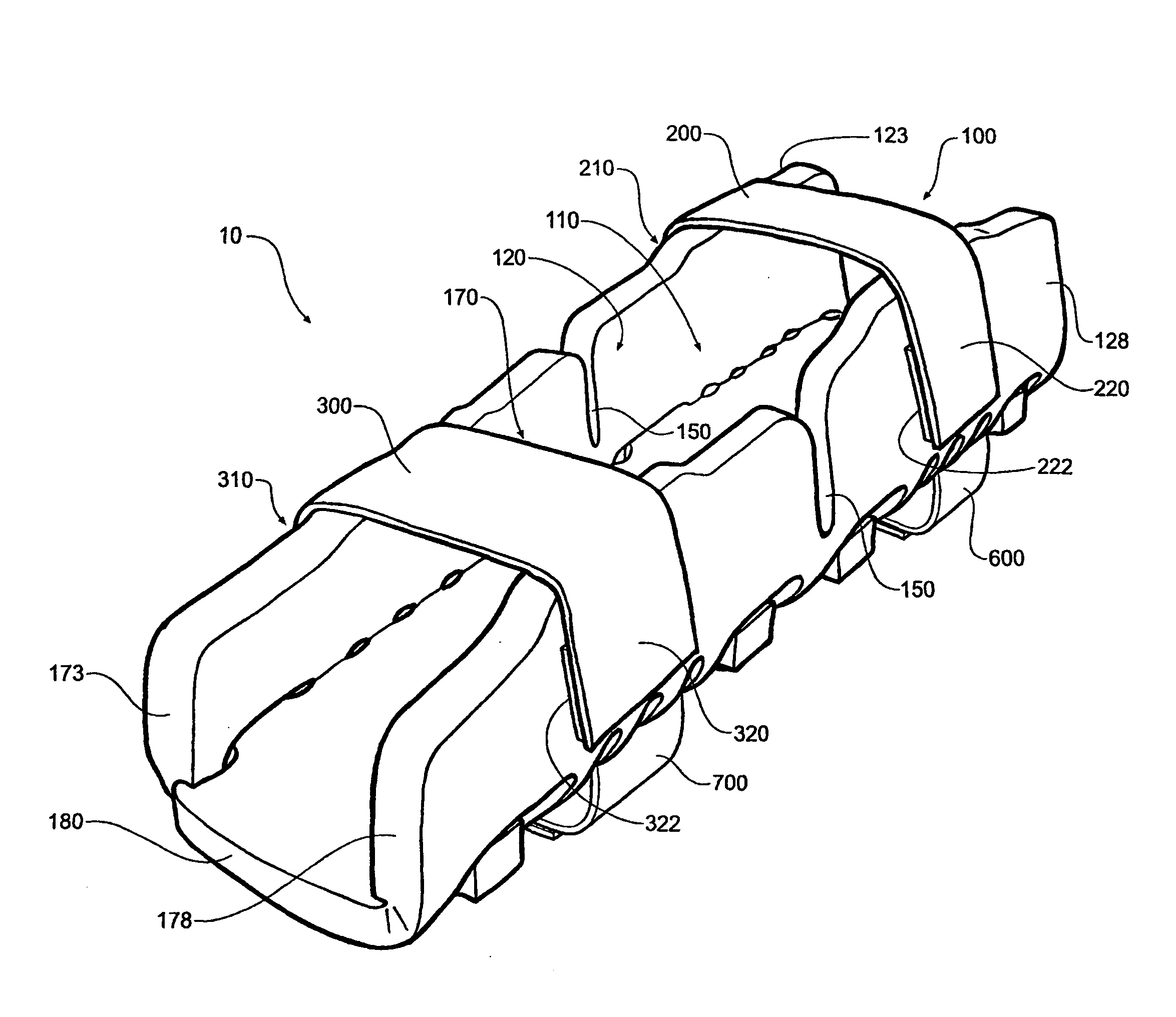
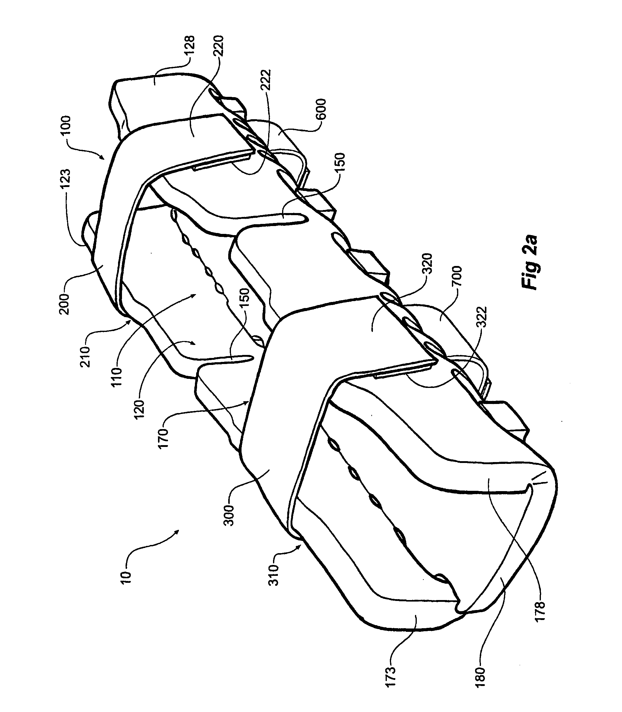
[0052]The arm protection apparatus of FIG. 4 has a channel 100 formed from the pliant foam of FIG. 3a which defines an upwardly opening mouth for receiving an arm. In this respect, the third embodiment illustrated in FIG. 4 is the same as the first embodiment of the invention illustrated in FIG. 2a. A first securing strap 600 for securing the channel 100 to an arm board 40 is provided. The first securing strap 600 has a first end 610 (more clearly shown in FIG. 5a) that is connected to a second side 128 of the upper arm receiving portion 120. The first securing strap 600 also has a second end 620 that is adapted for releasable engagement with the upper arm strap 200. In the embodiment illustrated, the adaption takes the form of a Velcro pad 625 com...

fourth embodiment

[0057]the invention is shown in FIGS. 6, 7a, 7b and 7c. With this embodiment, a channel 100 is again formed from the foam sheet of FIG. 3a. The channel 100 defines an upwardly opening mouth above a base 180 for receiving an arm. The channel 100 has an upper arm receiving portion 120 and a lower arm receiving portion 170. An upper arm strap 200 having a first end 210 connected to a first side of the upper arm receiving portion 120 and a second end 220 adapted for releasable engagement with a second side of the upper arm receiving portion 120 is also provided. Similarly, a lower arm strap 300 is also provided. In this respect, this embodiment of the invention is quite similar to the other embodiments described above. However, with this embodiment of the invention, a spine 580 under the base 180 of the channel 100 is provided. The spine 580 has a hinge 585 between the upper arm receiving portion 120 and the lower arm receiving portion 170. This embodiment of the invention is particular...


PUM


Abstract

The present invention relates to an arm protection apparatus, and particularly an apparatus for protecting an arm from pressure injury. The apparatus comprises a pliant material having receiving portions for the upper arm and lower arm and releasable straps for the upper and lower arm. Wherein, in use, the channel and straps surround the arm so as to distribute pressure on the arm and reduce the likelihood of pressure injury.

Description

CROSS-REFERENCE TO RELATED APPLICATION[0001]This application claims priority to Australian Patent Application No. 2008905768 filed Nov. 7, 2008. The entire contents of this application is hereby incorporated by reference.FIELD OF THE INVENTION[0002]The present invention relates to an arm protection apparatus and in particular to an apparatus for protecting an arm from pressure injury.BACKGROUND OF THE INVENTION[0003]In an active person, limbs can overcome poor positioning, excessive pressure and traction by reflexive withdrawal and repositioning of the affected limb. However, under anaesthetic or during emergency transport, patients have little or no control over the position of their limbs and thus rely on correct placement of such limbs by attending medical professionals. In a busy environment such as the operating theatre, limbs, in particular the arm, can be sited or can be moved to positions likely to cause damage to the limb. Such damage may include injury due to excessive pre...

Claims


Application Information

Patent Timeline
Patent Type & Authority Applications(United States)
IPC IPC(8): A61G15/00
CPCA61F5/05A61G13/12A61F5/37
Inventor SILFVERSKIOLD, KRIS
Owner SILFVERSKIOLD KRIS
Why Eureka
Try Eureka