
Seat cleaning-Capable Double -Seat Valve

a seat cleaning and double seat technology, applied in the direction of multiple way valves, valve arrangements, thin material handling, etc., can solve the problems of direct impact of seat cleaning flow on the surface delimiting the leakage cavity, best leakage resistance, and constant counterproductive effect of seat cleaning flow

Active Publication Date: 2011-05-05
GEA TUCHENHAGEN GMBH
View PDF2 Cites 3 Cited by
  • Summary
  • Abstract
  • Description
  • Claims
  • Application Information

AI Technical Summary

Benefits of technology

[0023]avoidance of a pressure-increasing direct pressurization of the seat area located in the closed position for the respective seat cleaning;
[0037]As further provided, the receiving cylinder described above is advantageously penetrated in a relocatable and concentric manner by a first displacement rod connected with the first closing element, designed as a hollow rod and inserted into the drive. At the inlet point into the receiving cylinder, the first displacement rod is sealed against it and it is designed as a first pressure compensation piston in the contact area with the receiving cylinder, the outer diameter of which reaches up to the outer diameter of the first closing element in the borderline case. The above arrangement permits the cleaning of the product-pressurized area of the receiving cylinder as well as those of the first displacement rod from within the first valve housing part in the flow.
[0048]The first opening slope suggested according to the invention facilitates the entry of the second seal into the cylindrical second seat and thereby reduces the wear on this second seal. However, from a flow point of view, this opening slope is more of a disadvantage because it delays the second seat cleaning flow by increasing the flow cross-section and thus represents a displacement risk for the flow. It is suggested in this connection to represent the first end section forming the first opening slope by at least one conical shell surface. So that the first seat cleaning flow is not deflected on the contour of this conical shell surface, it is suggested to tilt the first end section by a pitch, which is designed between 0 and 15 degrees, preferably between 5 and 15 degrees and here most preferably 15 degrees.
[0054]In order to avoid turbulence and dynamic pressure formation not only in the area of the seats of the double-seat valve described above, it is advantageous when all built-in components and hindrances in the remaining leakage cavity, if possible from a construction point of view, are avoided altogether. In this regard, another suggestion thus provides that the second displacement rod continues flying through the drainage hole and is permanently connected with the latter via at least one mainly radially oriented traverse at one end of the second closing element facing away from the first closing element. The otherwise conventional rods in the area of the leakage cavity and other connection means are thereby avoided and are relocated to an end located relatively far away from the leakage cavity, where they can no longer have disruptive impacts on the flow guidance.

Problems solved by technology

In the case of the known double-seat valve according to EP 0 646 741 A1, it is disadvantageous that it is at best leakage-resistant and not, as the title claims, leakage-free.
It is also disadvantageous that the respective seat cleaning flow, which makes its way through the rinsing agent passages at the associated housing stop and is primarily oriented axially / radially, pressurizes in a more or less uncontrolled and turbulent manner the seat seal located in the closed position.
Therefore, a direct impact of the seat cleaning flow on the surface delimiting the leakage cavity is always counterproductive.

Method used


Image

  • Seat cleaning-Capable Double -Seat Valve
  • Seat cleaning-Capable Double -Seat Valve
  • Seat cleaning-Capable Double -Seat Valve

Examples


first embodiment

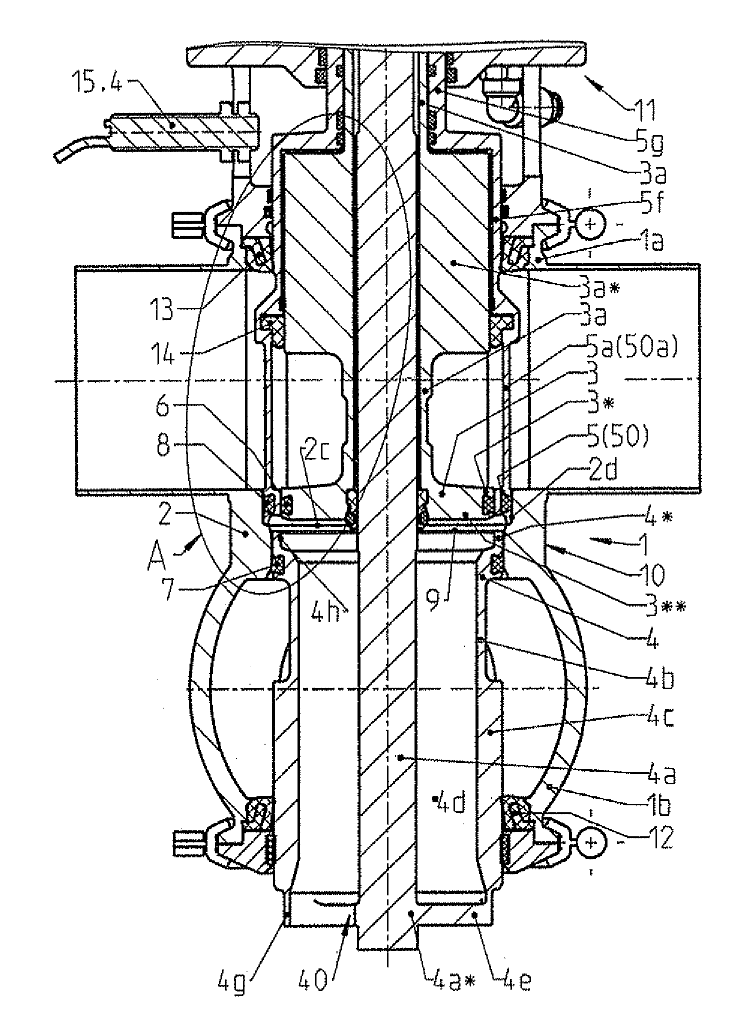
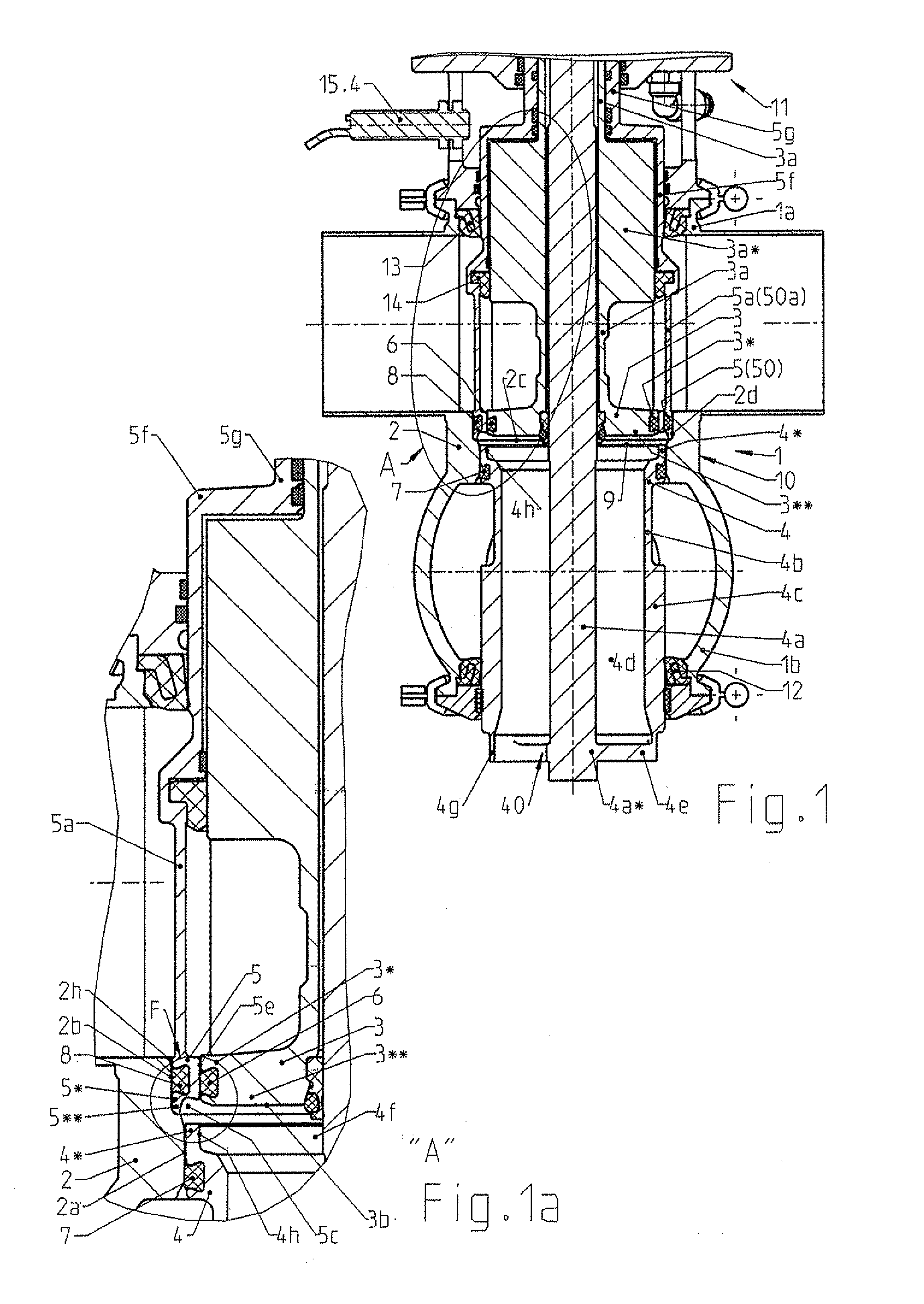
[0072]The double-seat valve 1 (FIGS. 1, 1a, 1b) according to the invention in an underlying first embodiment consists mainly of a valve housing 10 with a first valve housing 1a arranged on the top side, with respect to its vertical normal position, and a second valve housing 1b arranged below it, two independently movable closing elements 3 and 4 with the respectively arranged displacement rods 3a or respectively 4a and a first seat ring 2, which establishes a connection between the valve housing parts 1a, 1b via an inside connecting opening 2c.

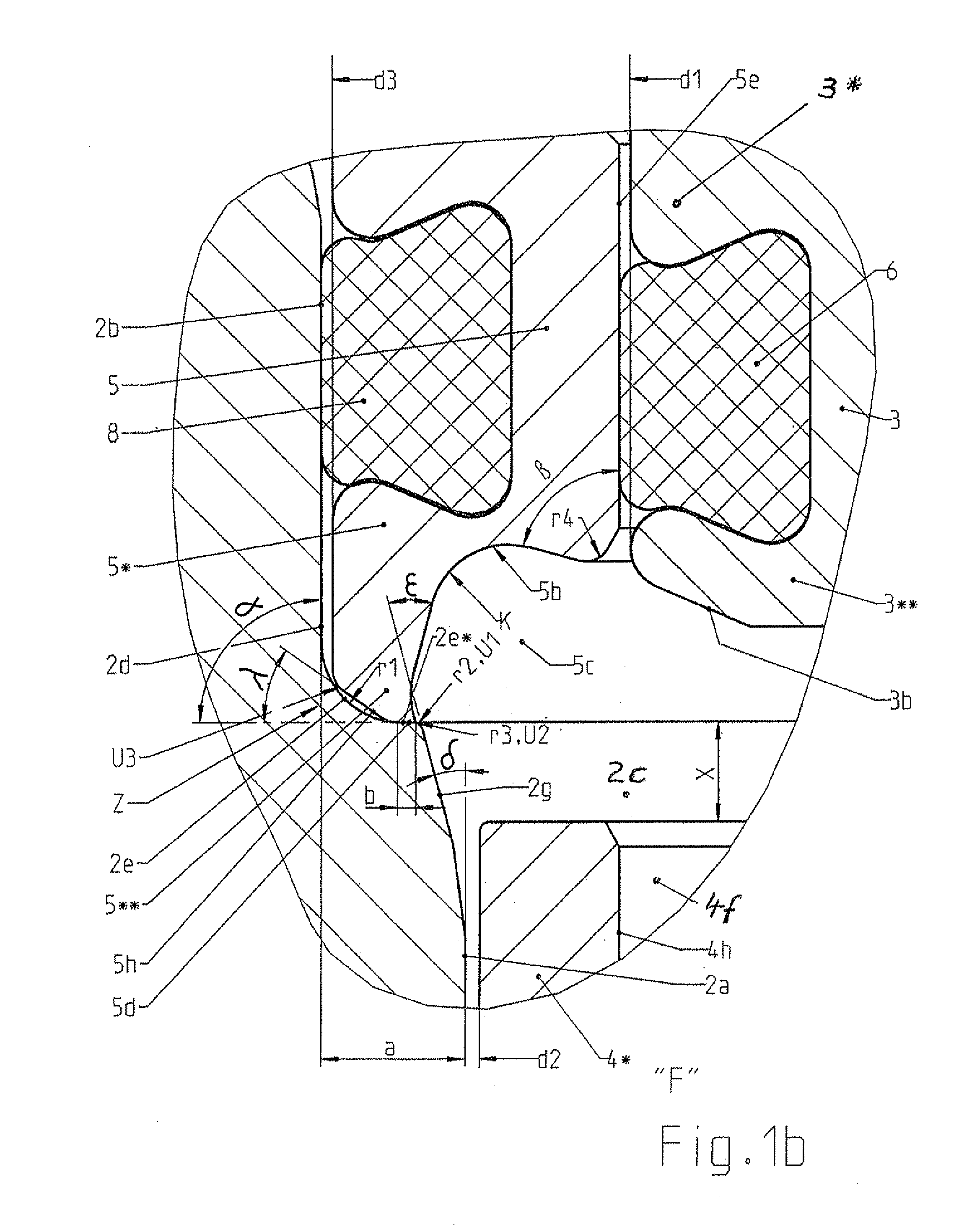
[0073]An axially relocatable, cylindrical ring-like slide part 5 is received radially outside in a sealing manner in a cylindrical third seat 2b designed in the upper part of the connecting opening 2c, which is formed there by a ring-like first recess 2d (FIGS. 1, 1b), and the slide part 5 forms radially inside a cylindrical first seat 5e, which runs coaxially to the connecting opening 2c, in a passage hole 5i (see FIG. 3) connected with the...

second embodiment

[0101]An underlying second embodiment of the double-seat valve 1 according to the invention is characterized in that there is now a fixed cylindrical second seat ring 50 in place of the axially relocatable, cylindrical, annular slide part 5 (FIG. 1). The embodiment with respect to this is not shown in FIG. 1, but rather only the reference numbers of the two modified components 50, 50a are specified at the locations in question. The second seat ring 50 is supposed in an unrelocatable manner via at least one modified connecting bar 50a in the first valve housing part 1a, and namely on its side lying opposite the second seat ring 2. A seat ring supported in this respect is generally known from EP 0 646 741 A1. Since the second seat ring 50 is axially unrelocatable, the seat cleaning of the first closing element 3 now takes place such that the first closing element 3 is transferrable to its seat cleaning position through a first partial lift T1 directed opposite the opening movement. Th...


PUM


Abstract

The invention relates to a seat cleaning-capable double-seat valve (1) with two serially arranged closing elements (3, 4), moveable relative to each other and designed as slide pistons, which prevent in the closed position of the double-seat valve (1) the overflow of fluids from one valve housing part (1a; 1b) into another (1b; 1a) through a connecting opening (2c) connecting the valve housing parts (1a, 1b) with each other and which border both in the closed and open position of the double seat valve (1) a leakage cavity (9), which is connected with the surroundings of the double-seat valve (1) via a tubular shaft (4b / 4c) arranged on a low-lying (with respect to a vertical normal position of the double-seat valve (1)), second closing element (4), in which a drainage hole (4d) is arranged. An axially relocatable, cylindrical annular slide part (5) is provided.

Description

CROSS-REFERENCE TO RELATED APPLICATIONS[0001]Not applicable.STATEMENT REGARDING FEDERALLY SPONSORED RESEARCH[0002]Not applicable.BACKGROUND OF THE INVENTION[0003]The invention relates to a seat cleaning-capable double-seat valve with two serially arranged closing elements, moveable relative to each other and designed as slide pistons, which prevent in the closed position of the double-seat valve the overflow of fluids from one valve housing part into another through a connecting opening connecting the valve housing parts with each other and which border both in the closed and open position a leakage cavity, which is connected with the surroundings of the double-seat valve via a tubular shaft arranged on the low-lying (in relation to a vertical normal position of the double-seat valve), second closing element, in which a drainage hole is arranged. The second, independently driven closing element is thereby designed larger than the first, independently driven closing element so that, ...

Claims


Application Information

Patent Timeline
Patent Type & Authority Applications(United States)
IPC IPC(8): F16K11/07
CPCF16K1/446Y10T137/4259Y10T137/8275Y10T137/8671Y10T137/88038
Inventor BURMESTER, JENSSUEDEL, MATTHIAS
Owner GEA TUCHENHAGEN GMBH
Learn More