
Knitting machines with air feed

a technology of air feed and knitting machine, which is applied in the field of knitting machines, can solve the problems of affecting the knitting process, unable to achieve the cleaning effect, and difficulty in accessing the cam, so as to reduce the air loss

Inactive Publication Date: 2007-06-07
GROZ BECKERT KG
View PDF9 Cites 3 Cited by
  • Summary
  • Abstract
  • Description
  • Claims
  • Application Information

AI Technical Summary

Benefits of technology

[0010] The air guidance space can be a more or less large gap between the cam assembly and the needle bed. In addition, the needle slots contribute considerably to the flow cross section of the air guidance space. Even if the otherwise existing gap between needle bed and cam assembly is reduced to nearly zero, considerable amounts of air can still flow through the needle slots which are not completely filled by the knitting tools. The knitting tools furthermore can be provided with airflow channels for reducing the flow resistance of the air in the needle slots. Finally, the cams themselves can have considerable flow cross-sections, which contribute to the air guidance space.
[0012] The guidance of the cleaning air stream in the space existing between the cam assembly and the needle bed furthermore permits not only the cleaning of the working parts of the knitting tools, but also the cleaning of the knitting tools and the needle slots. In particular, abraded material and dust which enters the cam region or which forms therein can be removed from the needle slots and the cams. The air guidance concept according to the invention consequently contributes to an improved operating safety and to reducing the wear and tear on the knitting machine. The cam region and the needle bed, meaning the needle cylinder, in particular can be kept free of abrasive particles.
[0014] The cam assembly normally consists of cams or cam segments, which are arranged on a cam base plate. In the case of a circular knitting machine, this cam base plate is ring-shaped and can consist of individual segments arranged one beside the other, wherein the cam segments adjoin with their narrow sides. Sealing means are provided between the cam segments of a preferred embodiment, so as to seal the cam segments against each other, wherein this measure reduces air losses. A suitable cover between the upper edge of the cam segment and the sinker ring can furthermore close off this air exit opening to conduct the cleaning air stream without losses into the stitch-forming region. However, air exit openings can also be purposely provided to allow the exit of a partial stream of the cleaning air. This measure can serve to purposely remove abrasion particles generated in the cam region of the cam assembly, without allowing the abrasive particles to reach the working parts of the knitting tools. For this purpose, it may be sufficient to omit the sealing means between two or more cam segments.

Problems solved by technology

In the process, dust and thread residues can collect on the knitting tools, which can interfere with the knitting process.
Since the complete cam assembly must be encased to generate the cleaning air stream, access to the cams is made more difficult.
No further cleaning effect is achieved.

Method used


Image

  • Knitting machines with air feed
  • Knitting machines with air feed
  • Knitting machines with air feed

Examples


Embodiment Construction

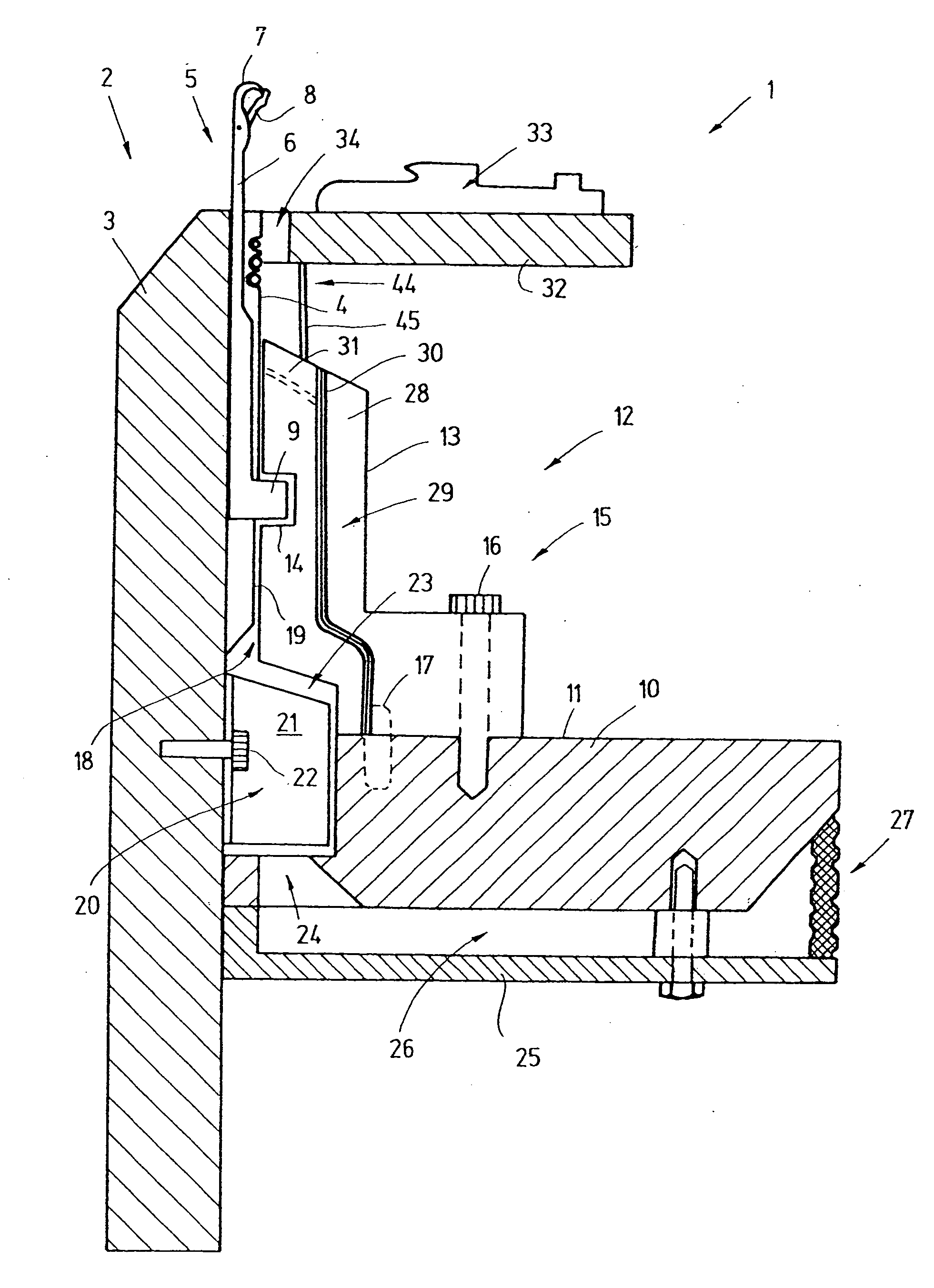
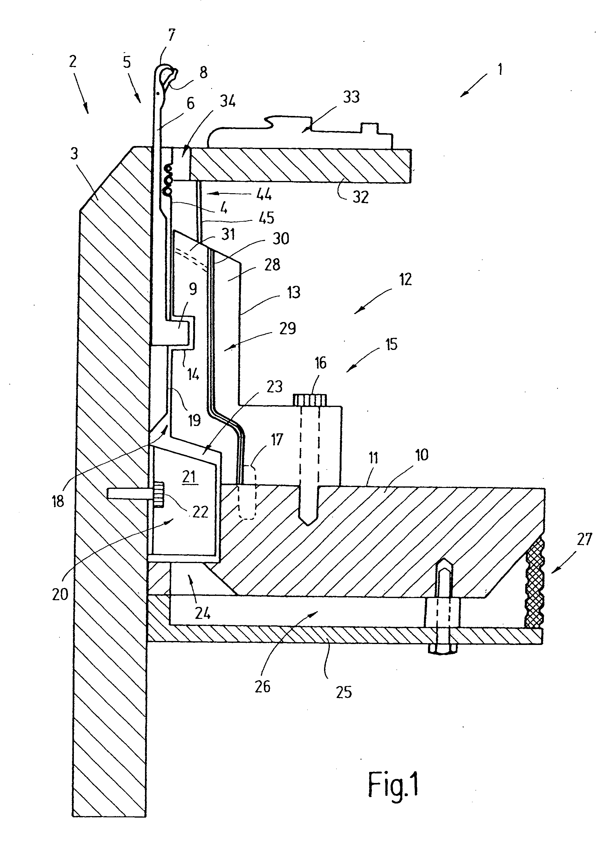
[0025] A knitting machine is illustrated in FIG. 1 with the exemplary embodiment of a circular knitting machine. Its needle bed 2 takes the form of a knitting cylinder 3, provided on its outside with vertical needle slots 4, meaning these extend parallel to its rotational axis. Knitting tools 5 are arranged inside the needle slots 4, e.g. in the form of the latch-type needles 6 shown herein, which can be displaced in longitudinal direction of the respective needle slot 4. The latch needle 6 is provided on one end with a hook 7 that projects from the needle slot 4 and comprises a latch 8, positioned pivoting. The shaft of the latch needle 6 extends inside the needle slot 4 and has a butt 9, which functions to drive the latch needle 6.

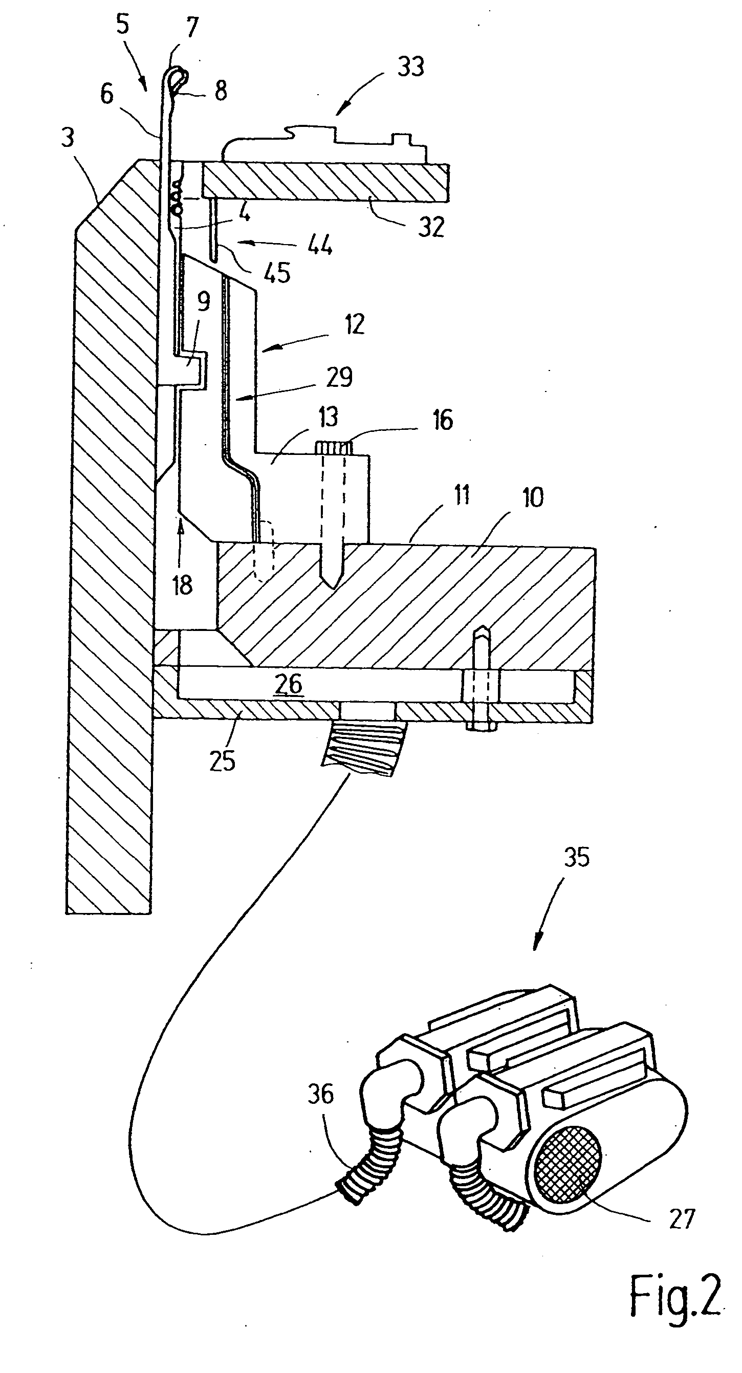
[0026] While the knitting cylinder 3 rotates during the operation, a ring-shaped cam base plate 10 that encloses the cylinder from the outside remains stationary. The cam base plate 10 is provided with a cam assembly 12 on its substantially flat surface...


PUM


Abstract

The knitting machine (1) according to the invention is provided with an air-conducting device (21) for conducting air into an air guidance space (18) that is embodied between the cam assembly (12) and the knitting cylinder (3). As a result of this air guidance space, cleaning air is supplied directly to the knitting tools (5), without requiring an outer casing around the cam assembly. In the same way, the air can also be guided between a dial and its associated cam assembly to corresponding dial needles or sinkers.

Description

CROSS REFERENCE TO RELATED APPLICATION [0001] This application claims the priority of German Patent Application No. 10 2005 057 354.1, filed on Dec. 1, 2005, the subject matter of which, in its entirety, is incorporated herein by reference. BACKGROUND OF THE INVENTION [0002] The invention relates to a knitting machine where air is supplied to the knitting tools. [0003] Knitting machines generally comprise a larger number of knitting tools, which are moved back and forth with the aid of suitable driving mechanisms to form a knitted fabric from guided threads. In the process, dust and thread residues can collect on the knitting tools, which can interfere with the knitting process. [0004] Document U.S. Pat. No. 5,737,942 discloses a circular knitting machine with a needle cylinder provided with a plurality of needle slots on the outside. Latch needles that are respectively provided with a butt are positioned inside of these slots. The butts of the latch needles project from the needle ...

Claims


Application Information

Patent Timeline
Patent Type & Authority Applications(United States)
IPC IPC(8): D04B35/32
CPCD04B35/32D04B35/00
Inventor STINGEL, UWE
Owner GROZ BECKERT KG
Learn More