Automotive paint applying installation and method using same

a technology for installing and painting vehicles, applied in the direction of superimposed coating process, liquid/solution decomposition chemical coating, manufacturing tools, etc., can solve the problems of large quantity of paint to fill, long pipe length, and large amount of paint to be applied, so as to reduce solvent consumption and limit paint losses

Inactive Publication Date: 2011-02-15
RENAULT SA
View PDF10 Cites 2 Cited by
  • Summary
  • Abstract
  • Description
  • Claims
  • Application Information

AI Technical Summary

Benefits of technology

[0016]The reduced dimensions of the secondary dispensing and recovery circuit serve to reduce the quantity of rare color paint used. Moreover, the scraper circulation system associated with the dispensing device serves to recover the excess rare color paint at the outlet of the painting stations and store it appropriately in a tank. This makes it unnecessary to circulate the paint in the circuit to prevent its deterioration, and only the paint tank is maintained with stirring. The use of flush valves between the secondary circuit and the connecting lines serves to improve the capacity to recover paint by the scrapers, the specific cleaning of these valves therefore being superfluous.
[0017]Furthermore, the independent bleed system of each connecting line permits its cleaning during the bleeding of the secondary circuit, without requiring the shutdown of the main color changers which dispense another paint color originating from a main circuit. Cleaning operations on the connecting line and the secondary circuit can thus be performed in masked time without affecting the production rate of the installation.
[0020]Advantageously, the scraper storage and circulating system comprises a storage trap of which the inlet and outlet are controlled by solenoid valves. The entry and exit of the scrapers can thus be automated.
[0021]Advantageously, the storage trap has a substantially L-shaped tubular shape, of which the upper and lower ends form the inlet and the outlet respectively, the scrapers being stored in the substantially vertical part. The scraper introduction and recovery system is thus compact, and suitable for rapidly and easily placing, by gravity, each scraper entering the trap, in a position in which it is ready to be reintroduced into the circuit.
[0027]The unused paint is thus recovered between each use, and the secondary circuit is cleaned, thereby considerably limiting the paint losses. The secondary circuit can then be used later to dispense paint of the same color, or another color.
[0028]Advantageously, the secondary circuit is rinsed by introducing two predetermined quantities of solvent separated by a scraper following a scraper according to the quantity of paint, at least part of the second quantity of solvent introduced being sent to the solvent tank using the dispensing device. Smaller quantities of solvent are thus used. The use of scrapers also serves to recover part of the second quantity of solvent and thereby reduce the solvent consumption.

Problems solved by technology

The frequent use of the paint colors demands large capacity paint tanks, which must consequently be kept at some distance from the application stations for reasons of size, so that long pipe lengths are necessary.
Due to the size of these dispensing circuits, a large quantity of paint is required to fill them (about 1 to 3 tons).
Dispensing circuits of this size are inconceivable for rarely used paint colors, especially since a small quantity of paint, about five liters, is needed to paint a car.
These colors are hence usually applied manually but with a finish inferior to that of the common colors applied automatically.
However, a non-negligible volume of paint is still necessary to load the dispensing circuit (several hundred liters) and the paint must be circulated permanently.
Moreover, if the consumption of paint is too low, the paint deteriorates so that the quality and color are no longer satisfactory, and the product must be destroyed and replaced.
Thus, up until the present, the automatic installations used to apply a rare color paint to a vehicle, to obtain a good quality finish, require quantities of paint which are disproportionate to the quantities actually applied, so that a large quantity of paint deteriorates.
Furthermore, space considerations around each color changer preclude the direct connection of a dispensing circuit to a changer valve, making it necessary to use a line connecting the circuit to the changer.
Such a bleed can only be obtained today using the color changer, implying the shutdown of the painting station and a decrease in the paint application rate in the installation.
However, these cleaning methods are only used on a short length of feed line, and not for a larger closed circuit.

Method used


Image

  • Automotive paint applying installation and method using same
  • Automotive paint applying installation and method using same
  • Automotive paint applying installation and method using same

Examples


Embodiment Construction

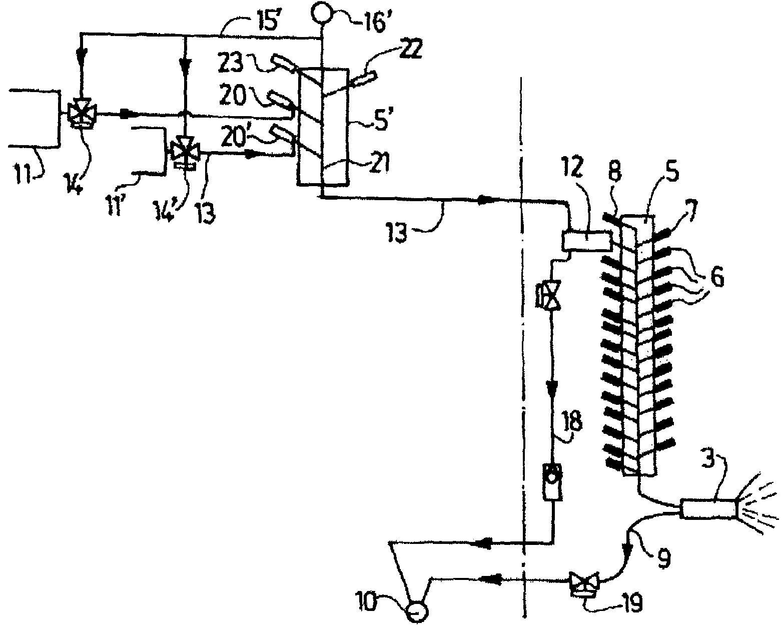
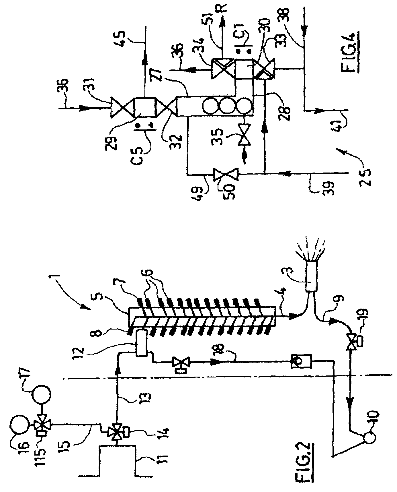
[0035]In these figures, the arrows indicate the fluid flow direction.

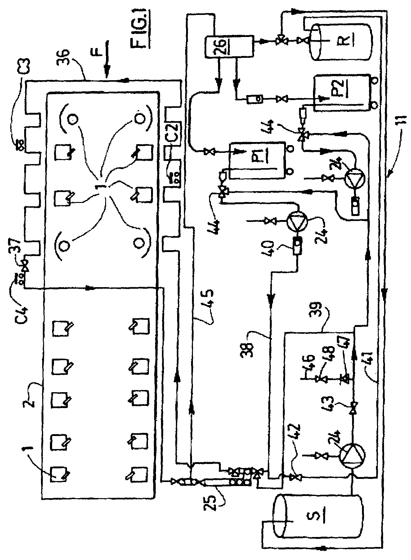
[0036]FIG. 1 shows an automobile painting installation according to the invention.

[0037]The installation comprises a plurality of painting stations 1, manual or robotized, arranged in a cabin 2 into which the vehicles to be painted are introduced in the direction of the arrow F in FIG. 1.

[0038]Each painting station 1 comprises an application device 3 supplied with paint via an outlet line 4 of a main color changer 5, as shown in FIG. 2. In this figure, the broken line represents the wall of the cabin 2. Each main paint changer 5 comprises a plurality of paint inlet valves 6.

[0039]Each inlet valve is connected on the one hand to a main paint dispensing circuit (not shown) and, on the other, to the paint outlet line 4. The main paint dispensing circuits are conventional and are not described. They are used to apply the commonly applied paint colors and referred to below as “common colors”. In practice, each valve is ...


PUM

PropertyMeasurementUnit
volumeaaaaaaaaaa
coloraaaaaaaaaa
colorsaaaaaaaaaa

Abstract

An automotive paint installation providing additionally to standard paint application, automated application of small rare color shade paint volumes. The installation includes at least a secondary rare color shade paint dispensing and recovery circuit, wherein scrapers are circulated in the part of the circuit supplying painting stations, and including a distribution device for directing the fluid exiting the painting stations towards paint, solvent, or recovery vessels. A plurality of connecting pipes connect each secondary circuit to a painting station, and are provided each with a bleeding system to enable recovery and bleeding to be performed during application of a current paint color shade. A rare color shade point dispensing and recovery method use such an installation.

Description

BACKGROUND[0001]The invention relates to an automobile painting installation and a method using such an installation.[0002]Installations for dispensing and applying paint to motor vehicles generally comprise a plurality of painting stations, manual or automatic, each connected to a plurality of paint dispensing circuits. Each paint dispensing circuit corresponds to a particular color and supplies each application station from a paint tank. The paint is circulated in the circuit to prevent it from deteriorating.[0003]At each application station, the paint color to be applied is selected by a color change device, called a color changer, comprising a plurality of valves of which the inlet is connected to a paint dispensing circuit by a line and of which the outlet is connected to a feed line connected to the paint application device of the station. Between two applications of paint of different colors, this feed line is rinsed using a bleed system. The opening of the color changer valv...

Claims


Application Information

Patent Timeline
Patent Type & Authority Patents(United States)
IPC IPC(8): B05C15/00B05B12/14B05B14/00B05B15/04
CPCB05B12/1481B05B12/149B05B15/0406B05B14/00
Inventor AGEORGES, GERARDMANDARD, THIERRY
Owner RENAULT SA
Why Eureka
Try Eureka