Utility pole with removable supporting push button

a technology of push button and utility pole, which is applied in the direction of rod connection, manufacturing tools, hoisting equipment, etc., can solve the problems of button assembly significant wear and tear, power circuit remains a very dangerous installation, and the danger is particularly acute, so as to achieve convenient maintenance

Inactive Publication Date: 2011-05-05
UTILITY SOLUTIONS
View PDF22 Cites 45 Cited by
  • Summary
  • Abstract
  • Description
  • Claims
  • Application Information

AI Technical Summary

Benefits of technology

[0028]The telescoping lineman's poles having the aforementioned push button and push button assembly are more conveniently maintained when used in combination with a tool that reaches into an open end of a telescoping lineman's pole, engages the push button and / or the push button assembly, and with the push button depressed to its most interior position within the inner diameter of the innermost telescoping section, allows for pulling an entire push button assembly out of the pole. Similarly, the push button assembly may be installed into a telescoping lineman's pole with the same tool. In an exemplary embodiment, the push button assembly includes a threaded bore. By threading the push button assembly onto the tool, the user pushes the entire push button assembly into the lineman's pole such that the push button is secured within corresponding openings in the pole sections. With the push button assembly in a locked position, the threaded tool is detached from the push button assembly. The same threading may be used to remove the push button and the push button assembly from an end of the lineman's pole without disassembling the entire device.

Problems solved by technology

Regardless of the machines, lifts, elevators, ladders, and extension devices that are available to the utility worker for use in service applications, a power circuit is still a very dangerous installation.
This danger is particularly acute during power outages when storms or accidents lead to damaged equipment that requires particular care.
This is compounded by the fact that service may be necessary in the dark of night when conditions are at their worst.
A recurring problem in these telescoping lineman's poles is that the button assemblies face significant wear and tear due to repetitive engagement and disengagement with the holes of the sections.
Another problem is that the button assemblies are difficult to replace without disassembling the whole unit.
The prior art does not address the accessibility of the buttons for installation or replacement.
Still, however, any repairs to the tab require full disassembly of the unit from the outside section inward.
As noted in prior devices, this interior arrangement is difficult to repair upon failure, as it requires entire disassembly of the entire unit.
One problem that arises in prior art lineman's poles is that the button assembly (13) connected to the last telescopic section (i.e., the section connected to the universal spline end (12)) eventually breaks over time due to repetitive use.
Unfortunately, to access the final telescopic section and its locking button (13), the entire telescopic pole (10) assembly must be disassembled, usually from the most proximal end relative to the user (i.e., the user slides each section out from the largest diameter bottom section).
This is a highly inefficient system of repair, and often the whole pole is replaced instead of the single button being repaired.
In that case, a simple button assembly malfunction leads to the cost of an entirely new lineman's pole.
Unfortunately, this model does not allow for replacing the button assembly (23) because the threading prevents the button from being removable.
The button assembly (23) simply does not fit through the end of the pole, so the user can not remove the old or install a new push button from the far end of the pole.
The problem, however, is that even with this arrangement, the button assembly (29) has no mechanism for pulling the button assembly out of the telescoping section without breaking the pole section in two.
The setup of FIG. 4, however, allows for no convenient mechanism or access to remove the push button assembly (29) from either the far end of the lineman's pole or from the insulated (20) lower portions of the sections.
None of these earlier developments, however, has shown a button assembly that can be easily accessed for replacement upon failure.

Method used


Image

  • Utility pole with removable supporting push button
  • Utility pole with removable supporting push button
  • Utility pole with removable supporting push button

Examples


Embodiment Construction

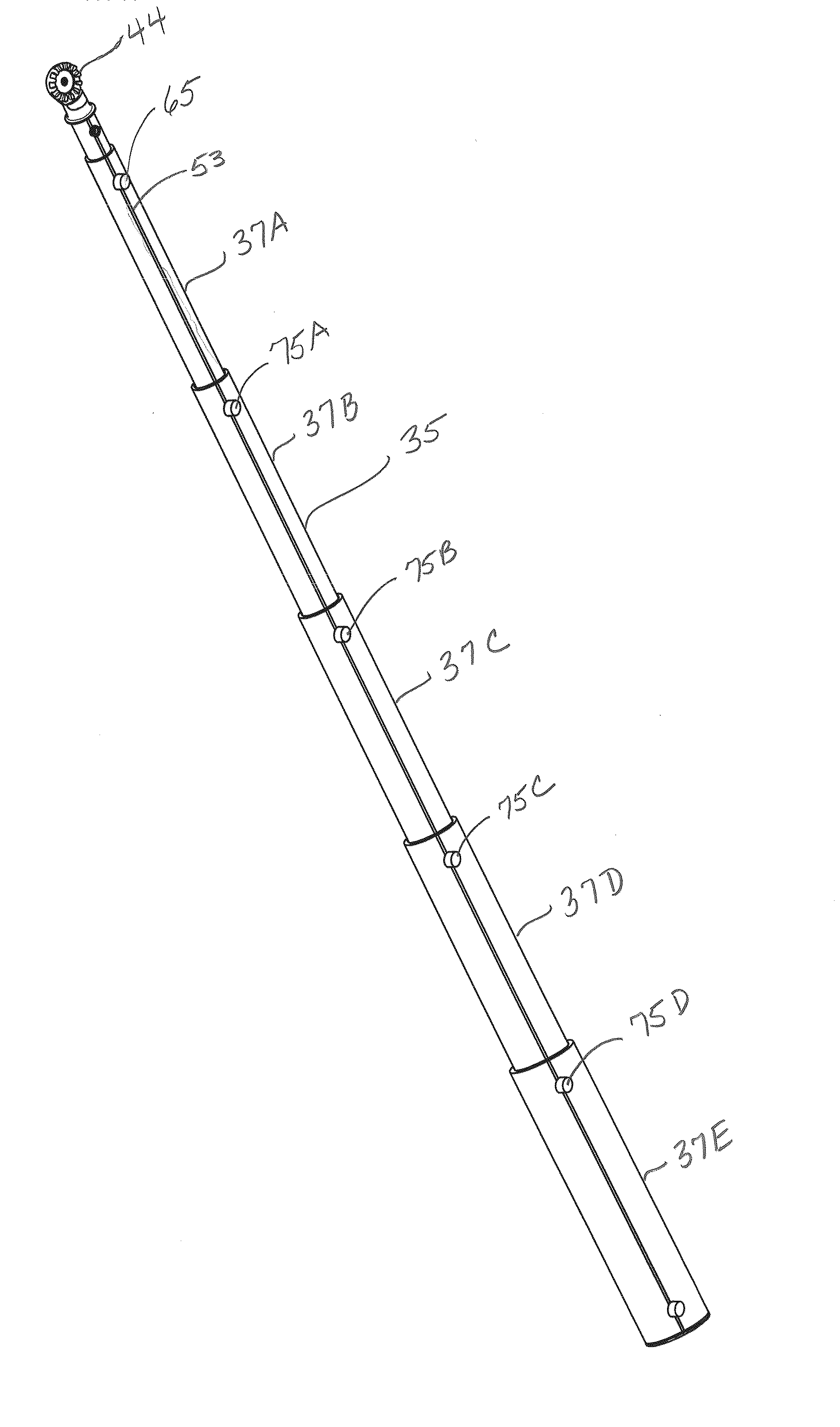
[0038]The lineman's pole, described in more detail below, can be viewed from the perspective of the lineman using the pole. From this perspective, the lineman's pole has a “proximal” end closest to the lineman and a “distal” end farthest from the lineman. The distal end, therefore, is typically the end that a lineman ultimately manipulates remotely to adjust an overhead or underground circuit that cannot be reached by hand. The proximal end is often the end having the telescoping section of the greatest diameter and allows the lineman to grip the pole with a steadier force than a thinner diameter would allow. One goal, of course, is to provide a pole that can be used with precision on a circuit element that is a significant distance from the user. After all, the most distal point on a lineman's pole will be used to replace the dexterity of a human hand in working on a circuit element.

[0039]The lineman's pole (35) shown in the figures consists of sections (37A-37E) that telescope tog...


PUM


Abstract

A lineman's pole having telescoping sections is connected by a push button assembly for temporarily fixing the length of the pole by holding sections together. The push button assembly is accessible from an end of the pole and can be installed, removed, and positioned via a connector accessible from one open end of the pole. A tool engages the connector on the push button, allowing for pulling, pushing, and rotating the button into a desired position. One connector includes a threading. A threaded tool engages the threads, allowing the user to pull the push button out of the telescoping pole. The connector, such as the threads within a bore in an adapter holding the push button, allows for removing the push button assembly. The push button assembly connects and releases cylindrical sections of the telescoping lineman's pole via openings in the surface of the telescoping sections.

Description

FIELD OF THE INVENTION[0001]The invention relates to hand-held, extendible lineman's poles for attaching tools to a distal end relative to the user. The lineman's poles are useful for servicing power circuits at elevations (or depths) that are difficult to reach. In particular, the invention relates to the buttons that are used to lock extendible, telescoping lineman poles in place at selectable fixed lengths for improved safety and accuracy in using tools attached to the poles.BACKGROUND OF THE INVENTION[0002]Working on a utility circuit requires highly specialized skill, training, and equipment. As would be expected, utility workers go to great lengths to ensure that utility circuits are handled safely. The market has accommodated the need for specialized safety equipment by providing utility workers with clothing (e.g. rubber and plastic garments for shock-proof attire), accessories (e.g., gloves, belts, and boots), eyewear, headwear, and hand tools that meet the needs of the pro...

Claims


Application Information

Patent Timeline
Patent Type & Authority Applications(United States)
IPC IPC(8): B25G1/04B25J1/00F16B7/10B25J1/04F16B7/12H02G1/02
CPCB25G1/04F16B7/105Y10T403/32483Y10T403/32475Y10T16/473H02G1/02
Inventor NOLTE, MATTHEWWOOD, EUGENENOLTE, MICHAEL
Owner UTILITY SOLUTIONS
Why Eureka
Try Eureka