Vibration actuator

a technology of vibration actuator and actuator, which is applied in the direction of electrical apparatus, dynamo-electric machines, etc., can solve the problems of low shock resistance of this vibration actuator, difficulty in producing a low-profile vibration actuator, and increased length of the frame body along the central axis, so as to achieve high drop-impact resistance, simple structure, and efficient and uniform vibration

Inactive Publication Date: 2011-05-05
COPAL CO LTD
View PDF4 Cites 62 Cited by
  • Summary
  • Abstract
  • Description
  • Claims
  • Application Information

AI Technical Summary

Benefits of technology

[0006]An object of the present invention is to provide a vibration actuator that has a low profile, a simple structure, and a high drop-impact resistance.
[0008]The vibration actuator includes the coil, which extends in the vibration direction and has a flat shape, and the magnet, which extends in the vibration direction and has a flat shape, so that the case can be made flat or low profile. As compared with a vibration motor in which a magnet rotates, sharp and strong vibration can be produced with the vibration generator according to the present invention, in which the magnet linearly vibrates in in-plane direction. Moreover, the weight portion is supported by the shaft. Therefore, when a drop impact is applied, the weight portion can move along the shaft. Thus, the weight portion is not freely moved in the case, so that complex shock absorbing means for absorbing the impact of a collision between the case and the weight portion is not necessary, and malfunctioning of the vibration actuator due to deforming of the weight portion that may be caused by the collision is unlikely to occur. Therefore, the vibration actuator has a high drop-impact resistance with a simple structure. The spring is disposed between the spring receiving portion and the weight portion. Therefore, there is no unnecessary space in the case, so that space can be saved and the vibration actuator can be made compact. The vibration actuator has a high-efficiency, and vibration having long repetition life can be generated in a small space.
[0010]Thus, the weight portions are disposed so that the magnet is interposed therebetween. Therefore, well-balanced vibration can be generated. A coil spring having a large free length can be used. Therefore, the spring easily resonate, and large vibration can be obtained with a small driving power.
[0012]The coil springs, which naturally have hysteresis, are disposed between the first weight portion and the second weight portion with the spring receiving portion interposed therebetween. Therefore, well-balanced vibration can be generated. Moreover, because a load due to vibration is shared by the coil springs, whereby the durability and the life of the springs are increased.
[0014]By using the first and second yoke plates that are disposed parallel to each other, an optimal magnetic circuit is formed in the case and efficient and uniform vibration can be generated in in-plane direction while maintaining the low-profile of the vibration actuator.
[0015]According to the present invention, a vibration actuator having a low-profile, a simple structure, and a high drop-impact resistance can be provided.

Problems solved by technology

However, because the yoke of the vibration actuator described above vibrates along the central axis of the frame body having a cylindrical shape, in order to increase the amplitude of the vibration of the yoke, the length of the frame body along the central axis needs to be increased, which makes it difficult to produce a low-profile vibration actuator.
Therefore, if the vibration actuator were dropped, it is highly likely that the yoke would violently collide with the frame body, so that shock resistance of this vibration actuator is low.
As a result, a problem arises in that the structure of the vibration actuator becomes complex.

Method used


Image

  • Vibration actuator
  • Vibration actuator
  • Vibration actuator

Examples


Embodiment Construction

[0024]Hereinafter, a vibration actuator according to embodiments of the present invention will be described in detail.

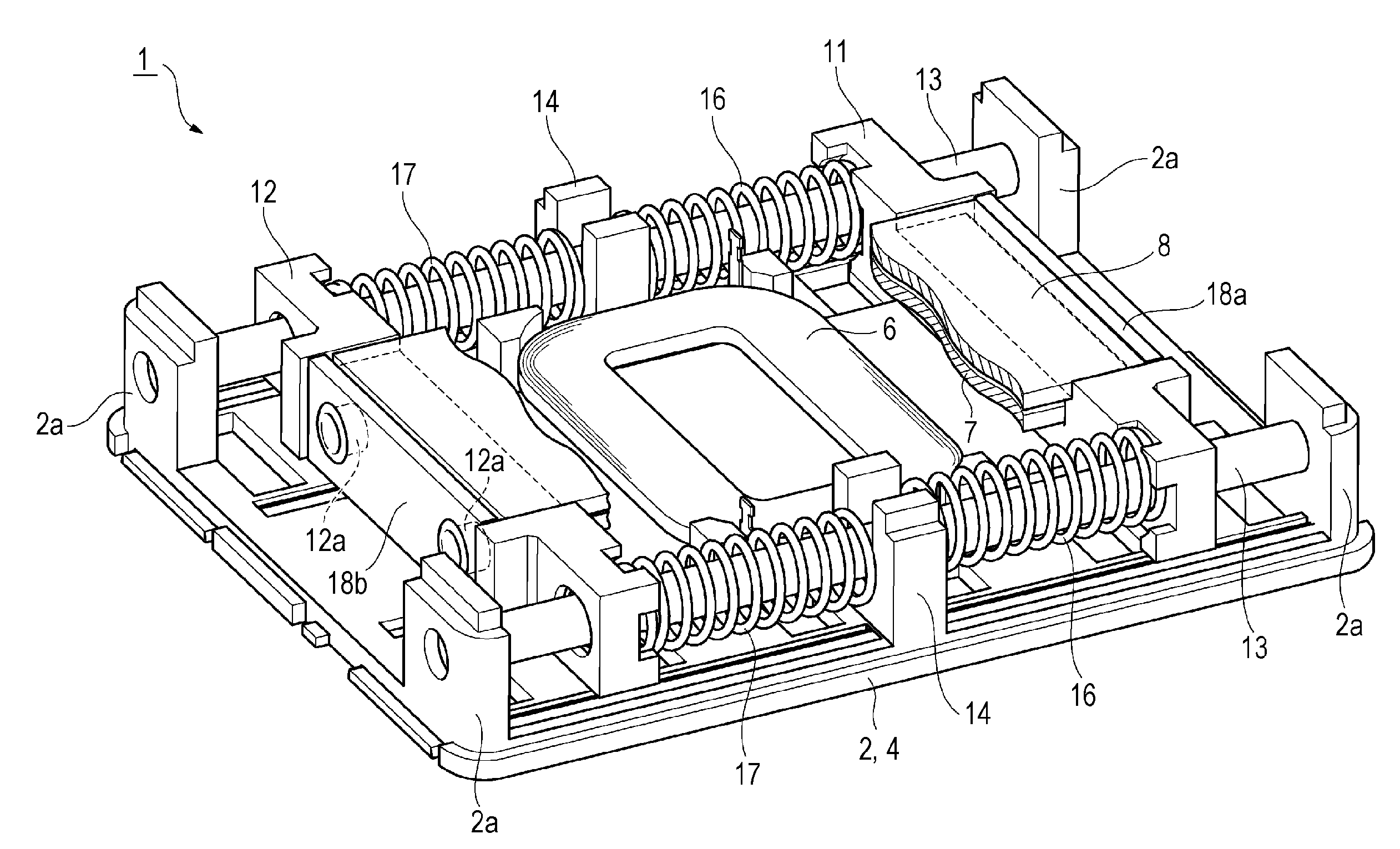
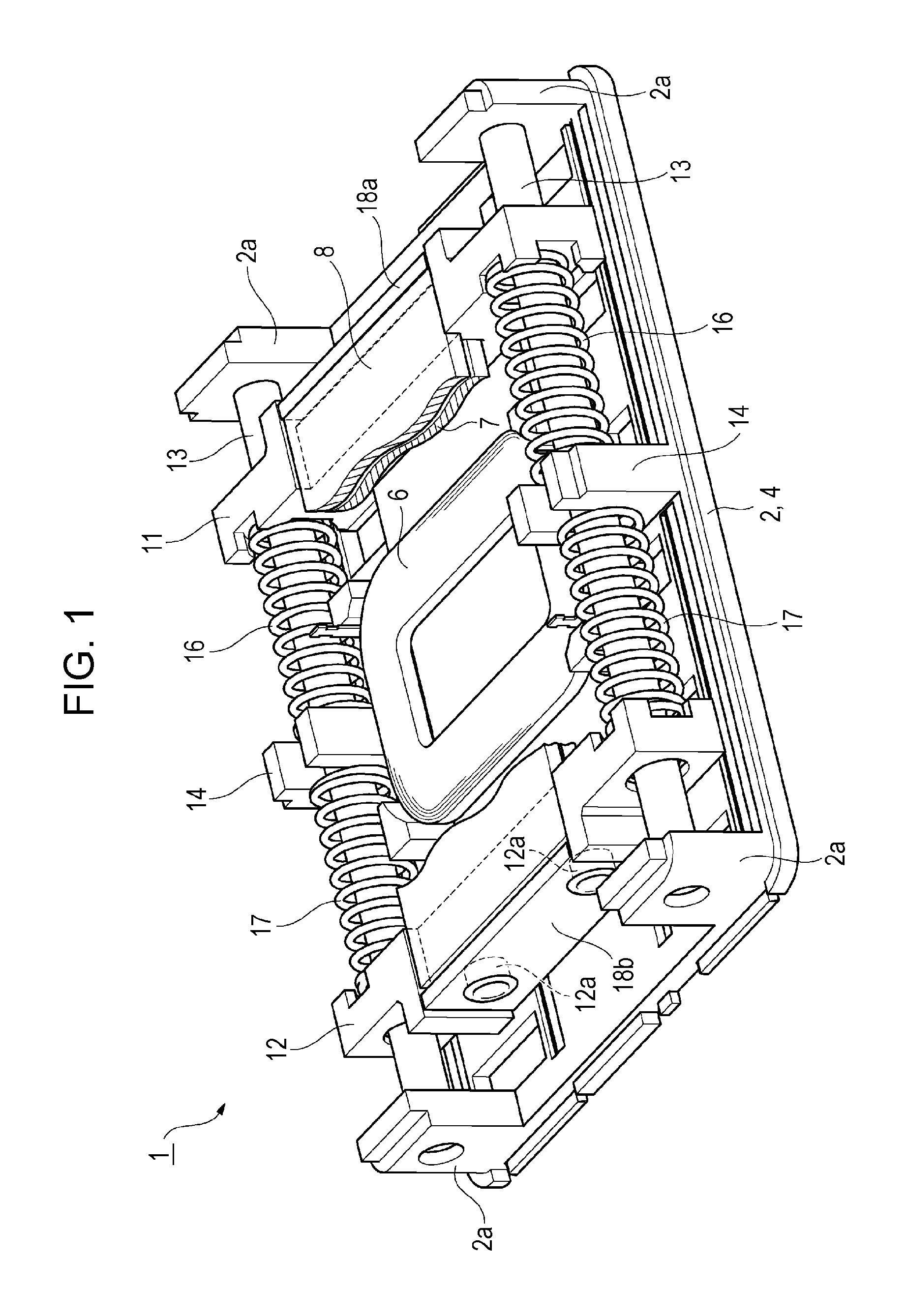
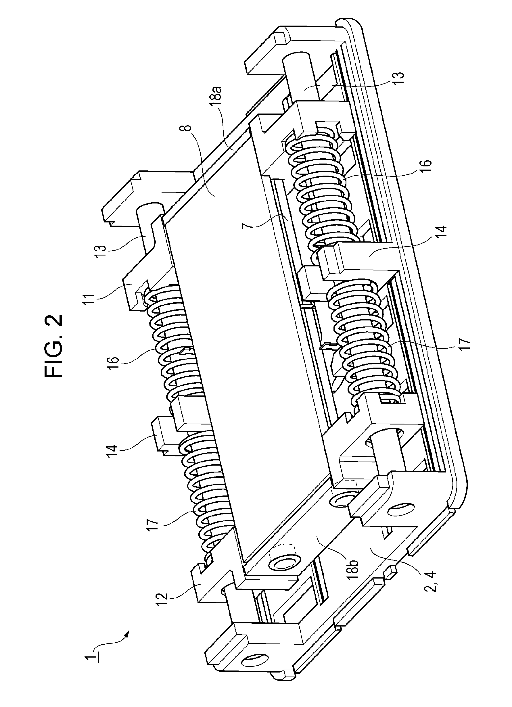
[0025]Referring to FIGS. 1 to 5, a vibration actuator 1 includes a case 4 having a flat shape. The case 4 includes a base plate 2 and a lid portion 3. The case 4 contains a coil 6 and a magnet 7. The coil 6 has a flat annular shape and is fixed to the base plate 2. The magnet 7 has a flat plate-like shape and is disposed so as to face the coil 6. The magnet 7 includes magnet portions 7a and 7b. Each of the magnet portions 7a and 7b is magnetized so that one of the planes thereof is the north pole and the other of the planes thereof is the south pole. The magnet 7 is made by bonding the side surfaces of the magnet portions 7a and 7b to each other in such a way that the north pole of the magnet portion 7a faces the south pole of the magnet portion 7b in in-plane direction. The magnet 7 may be made by magnetizing a single magnetic plate.

[0026]The coil 6 is connected to ...


PUM


Abstract

A vibration actuator includes a coil that extends in a vibration direction and has a flat shape and a magnet that extends in the vibration direction and has a flat shape, so that a case can be made flat or low profile. A weight portion is supported by a shaft, so that, when a drop impact is applied, the weight portion can move along the shaft and the weight portion is not freely moved in the case. A coil spring is disposed between a spring receiving portion and a weight portion. Therefore there is no unnecessary space in the case, so that space can be saved and the vibration actuator can be made compact.

Description

BACKGROUND OF THE INVENTION[0001]1. Field of the Invention[0002]The present invention relates to a vibration actuator having a compact size, which is used as a vibration generator for notifying a user of an incoming call to a mobile wireless apparatus such as a mobile phone, or as a vibration generator for providing tactile sensation of a touch panel or the reality of a games machine to a user's finger or hand.[0003]2. Description of the Related Art[0004]Japanese Unexamined Patent Application Publication No. 10-117472 describes a technology in such a field. FIG. 1 of that publication illustrates a vibration actuator including a frame body and a soft elastic body that is fixed to the inner surface of the frame body. A cylindrical yoke, which is made of a magnetic substance, is disposed in the frame body. The yoke also serves as a weight for generating vibration, and is supported by a plate spring in the case. The plate spring has a shape like a conical spiral. The plate spring is fix...

Claims


Application Information

Patent Timeline
Patent Type & Authority Applications(United States)
IPC IPC(8): H02K33/00
CPCH02K33/16
Inventor ODAJIMA, SHINSEGAWA, NOBORUTONOGAI, YOSHIHIDEYAMAWAKI, RYUTAHOSHINA, TOMOAKI
Owner COPAL CO LTD
Why Eureka
Try Eureka