Vibration motor

Inactive Publication Date: 2011-05-05
SAMSUNG ELECTRO MECHANICS CO LTD
View PDF2 Cites 44 Cited by
  • Summary
  • Abstract
  • Description
  • Claims
  • Application Information

AI Technical Summary

Benefits of technology

[0009]The present invention provides a vibration motor that can prevent a concentrat

Problems solved by technology

In the conventional leaf spring, however, stresses are concentrated where a portion contacted by and coupled to a supporting part, such a

Method used


Image

  • Vibration motor
  • Vibration motor
  • Vibration motor

Examples


Embodiment Construction

[0027]The features and advantages of this invention will become apparent through the below drawings and description.

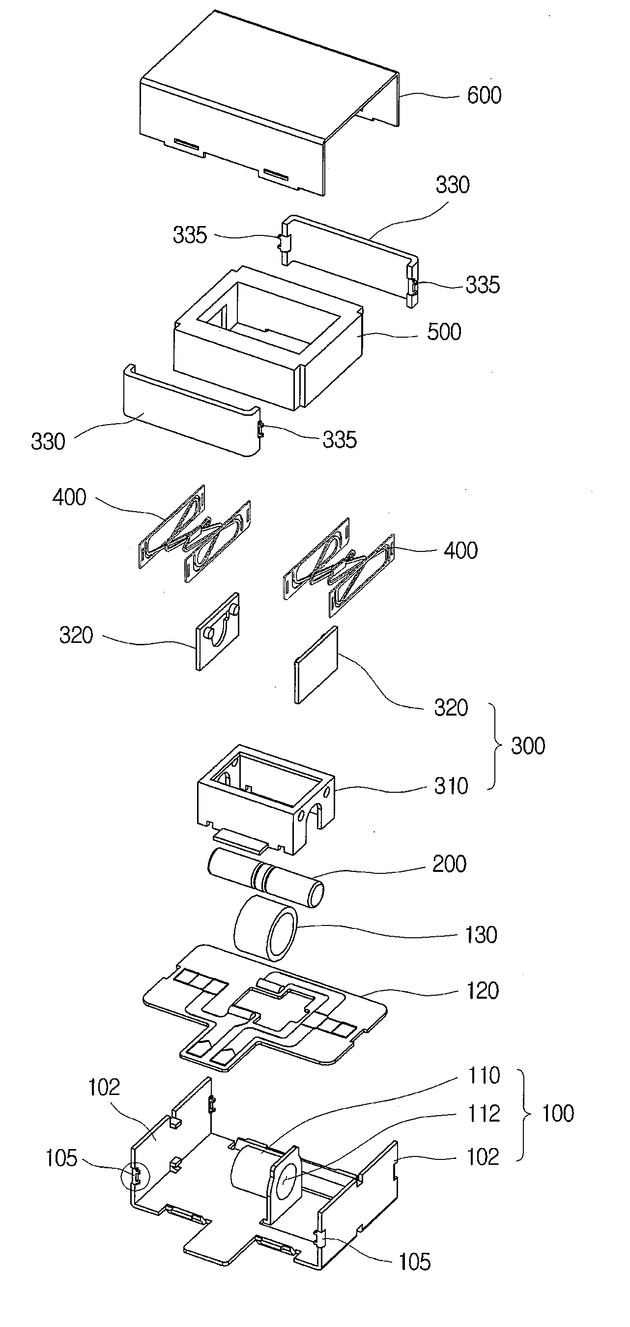
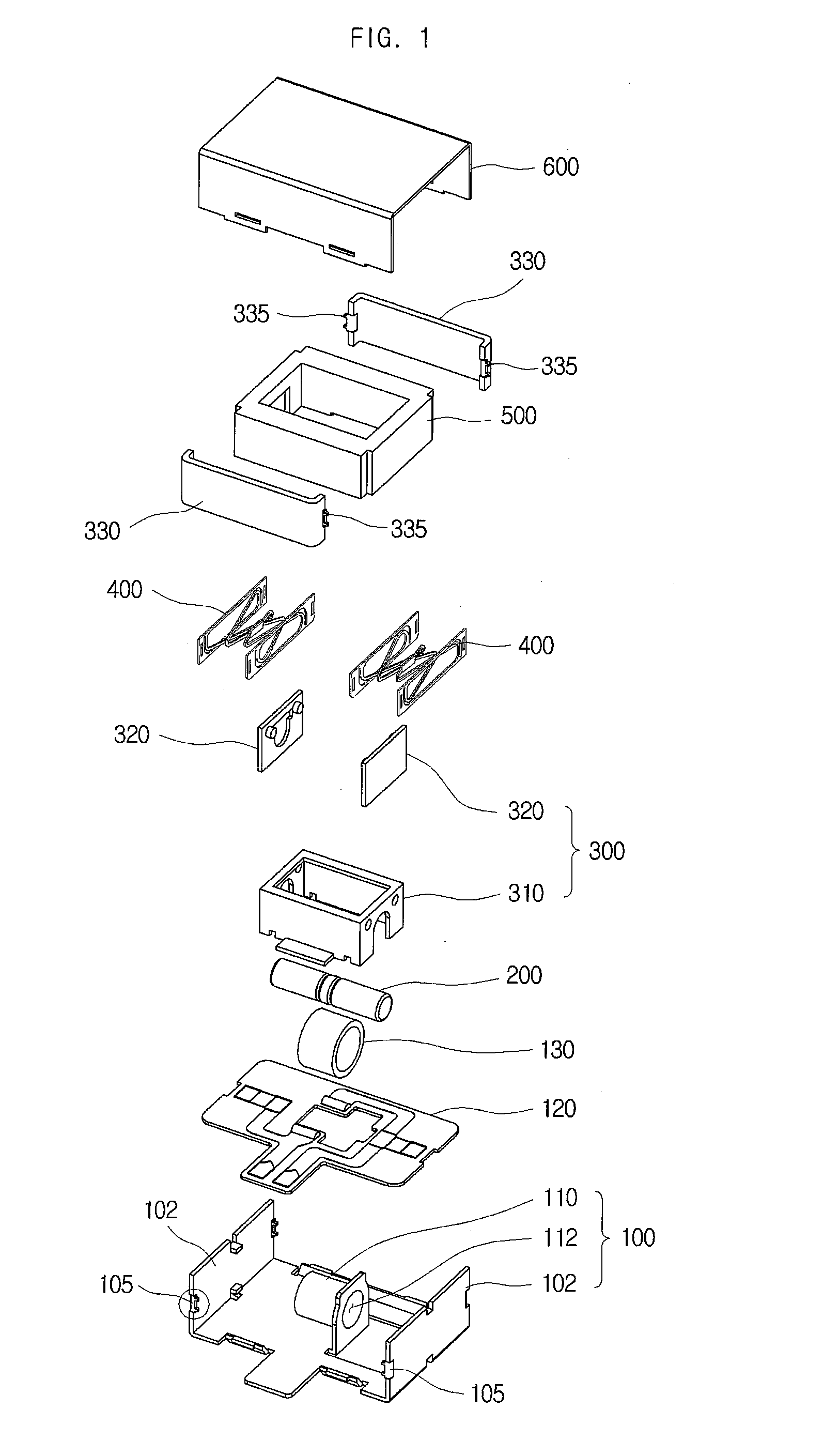
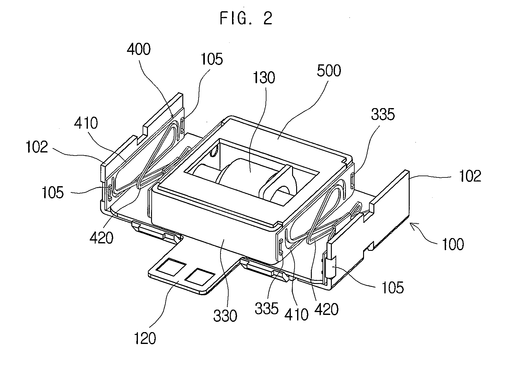
[0028]FIG. 1 is an exploded perspective view of a vibration motor in accordance with an embodiment of the present invention; FIG. 2 is a perspective view of a vibration motor in accordance with an embodiment of the present invention; and FIG. 3 is a plan view of a vibration motor in accordance with an embodiment of the present invention.

[0029]A vibration motor in accordance with an embodiment of the present invention includes a base 100, a vibrator, coupling parts 105 and 335 and a leaf spring 400. A coil unit 130 is disposed in the base 100, and the vibrator can be constituted by a magnet 200, a weight 500 and a yoke 300.

[0030]The base 100 is a part that supports the vibrator, which will be described later, to vibrate. In this embodiment, the base 100 can have a space in which components constituting the vibration motor can be housed. The coil unit 130, which will be ...


PUM


Abstract

A vibration motor is disclosed. In accordance with an embodiment of the present invention, the vibration motor includes a base, a vibrator, which reciprocates, a coupling part, which is protruded on at least one of the base and the vibrator, and a leaf spring, which includes a frame and an elastic part. Here, the frame is coupled to the coupling part and disposed apart from the base or the vibrator in which the coupling part is formed, and the elastic part is extended from the frame and elastically supports the vibrator. Thus, the leaf spring can be prevented from having concentrated stress and damage occurred, thereby improving the lifetime of the leaf spring.

Description

CROSS-REFERENCE TO RELATED APPLICATIONS[0001]This application claims the benefit of Korean Patent Application No. 10-2009-0104783, filed with the Korean Intellectual Property Office on Nov. 2, 2009, the disclosure of which is incorporated herein by reference in its entirety.BACKGROUND[0002]1. Technical Field[0003]The present invention is related to a vibration motor.[0004]2. Description of the Related Art[0005]A vibration motor is a part that converts electrical energy into mechanical vibrations by using the principle of generating electromagnetic forces, and is commonly installed in a mobile phone to generate a soundless vibrating alert. With the rapid expansion of mobile phone markets and increased functionalities added to the mobile phone, mobile phone parts are increasingly required to be smaller and better. As a result, there has been an increased demand for the development of a new structure of vibration motor that can improve the shortcoming of conventional vibration motors a...

Claims


Application Information

Patent Timeline
IPC IPC(8): H02K33/00
CPCH02K33/16H02K1/17H02K33/02
Inventor LEE, KYOUNG-HOOH, HWA-YOUNGLEE, JEE-SUNGPARK, SEOK-JUNBANG, JE-HYUNLEE, KWANG-HYUNGKIM, YONG-JINCHOI, JUN-KUN
Owner SAMSUNG ELECTRO MECHANICS CO LTD
Why Eureka
Try Eureka