Magnetic field sensor measuring a direction of a magnetic field in a plane and current sensor

a magnetic field and current sensor technology, applied in the direction of magnetic field magnitude/direction, voltage/current isolation, measurement devices, etc., can solve the problem of difficult selective measurement of magnetic field in a signal, and the auxiliary magnetic field must be of equal size as the magnetic field produced by the primary current, so as to achieve high accuracy

Inactive Publication Date: 2011-05-05
SENIS
View PDF2 Cites 23 Cited by
  • Summary
  • Abstract
  • Description
  • Claims
  • Application Information

AI Technical Summary

Benefits of technology

[0020]With a magnetic field sensor with which the number of contacts of the first sensing structure is eight, the number of contacts of the second sensing structure is eight and which is operated such that the Hall elements complete each term in four steps...

Problems solved by technology

The drawback of this implementation is that the value of the auxiliary magnetic field is low, that the auxiliary magnetic field runs in the same direction as the primary current's magnetic field, which makes it difficult to selectively measure it in a signal comprising both the primary current's magnetic field an...

Method used


Image

  • Magnetic field sensor measuring a direction of a magnetic field in a plane and current sensor
  • Magnetic field sensor measuring a direction of a magnetic field in a plane and current sensor
  • Magnetic field sensor measuring a direction of a magnetic field in a plane and current sensor

Examples


Embodiment Construction

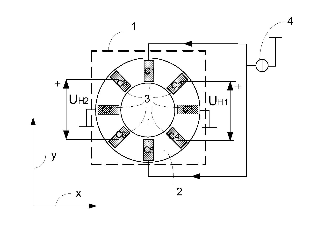
[0030]FIG. 1 shows a planar sensing structure 1 consisting of a ring-shaped, electrically conductive well 2 and a number N of at least eight contacts 3 of equal size placed at equal distance from each other along the ring-shaped well 2 and contacting the ring-shaped well 2. The ring-shaped well 2 has a first conductivity type and is embedded in a well or a substrate of a second conductivity type. The sensing structure 1 lies in a plane, the axis of which are designated as x and y. Such a sensing structure 1 and its operation as a moving Hall element are known from the international patent application WO 2008145662. With a preferred embodiment, as shown in FIG. 1, the number N of the contacts 3 is N=8. The eight contacts 3 are labeled as C1 to C8. In this embodiment, the eight contacts 3 are—as seen from the center of the ring-shaped well 2—angularly displaced by 45°.

[0031]Although the number N of the contacts 3 is very small, five contacts lying adjacent each other, i.e. a first, se...


PUM


Abstract

A magnetic field sensor for measuring a direction of a magnetic field in a plane comprises two sensing structures (1A; 1B) that can be operated as a rotating Hall element. The two Hall elements are rotated in discrete steps in opposite directions. Such a magnetic field sensor can be used as current sensor for measuring a primary current flowing through a conductor (15).

Description

FIELD OF THE INVENTION[0001]The invention concerns a magnetic field sensor measuring a direction of a magnetic field in a plane and a current sensor having such a magnetic field sensor.BACKGROUND OF THE INVENTION[0002]The measurement principle of the present invention is based on the one hand on the measurement of a magnetic field produced by the current to be measured which is called the primary current and on the other hand on the measurement of an auxiliary magnetic field produced by a secondary current flowing through a coil. The current sensor therefore comprises a magnetic field sensor, such as e.g. a Hall device, a fluxgate sensor or a magnetoresistive sensor like an AMR or GMR sensor. In the prior art, the magnetic field produced by the current to be measured and the auxiliary magnetic field produced by the secondary current flowing through the coil run in the same direction and the magnetic sensor is a single axis sensor the sensitive axis of which is collinear with this di...

Claims


Application Information

Patent Timeline
IPC IPC(8): G01R33/06
CPCG01R15/18G01R33/07G01R33/077G01R33/075G01R33/072
Inventor POPOVIC, RADIVOJEBANJEVIC, MIRJANA
Owner SENIS
Why Eureka
Try Eureka