
Focal-plane shutter apparatus and image-pickup apparatus

a shutter and optical plane technology, applied in shutters, still video cameras, television systems, etc., can solve the problems of increasing power consumption of trailing blades, affecting normal image capture, and long time required for returning the leading blade driving lever to the charged position, so as to reduce power consumption and release the effect of tim

Inactive Publication Date: 2011-05-05
CANON KK
View PDF2 Cites 9 Cited by
  • Summary
  • Abstract
  • Description
  • Claims
  • Application Information

AI Technical Summary

Benefits of technology

[0011]The present invention provides a focal-plane shutter apparatus capable of reducing power consumption during the live-view display and a release time lag, and provides an image-pickup apparatus with the same.

Problems solved by technology

On the other hand, although it is necessary to also maintain the trailing blades in the opened state, continuous energization to the electromagnet for the trailing blades increases power consumption.
However, since the angular areas where the inclination portions for the leading and trailing blade driving levers are formed on the cam member are equal to each other and a rotation speed of the motor is slow, a time required for returning the leading blade driving lever to the charged position becomes long.
Therefore, a release time lag from a release instruction to exposure becomes long in a normal image capturing.

Method used


Image

  • Focal-plane shutter apparatus and image-pickup apparatus
  • Focal-plane shutter apparatus and image-pickup apparatus
  • Focal-plane shutter apparatus and image-pickup apparatus

Examples


embodiment 1

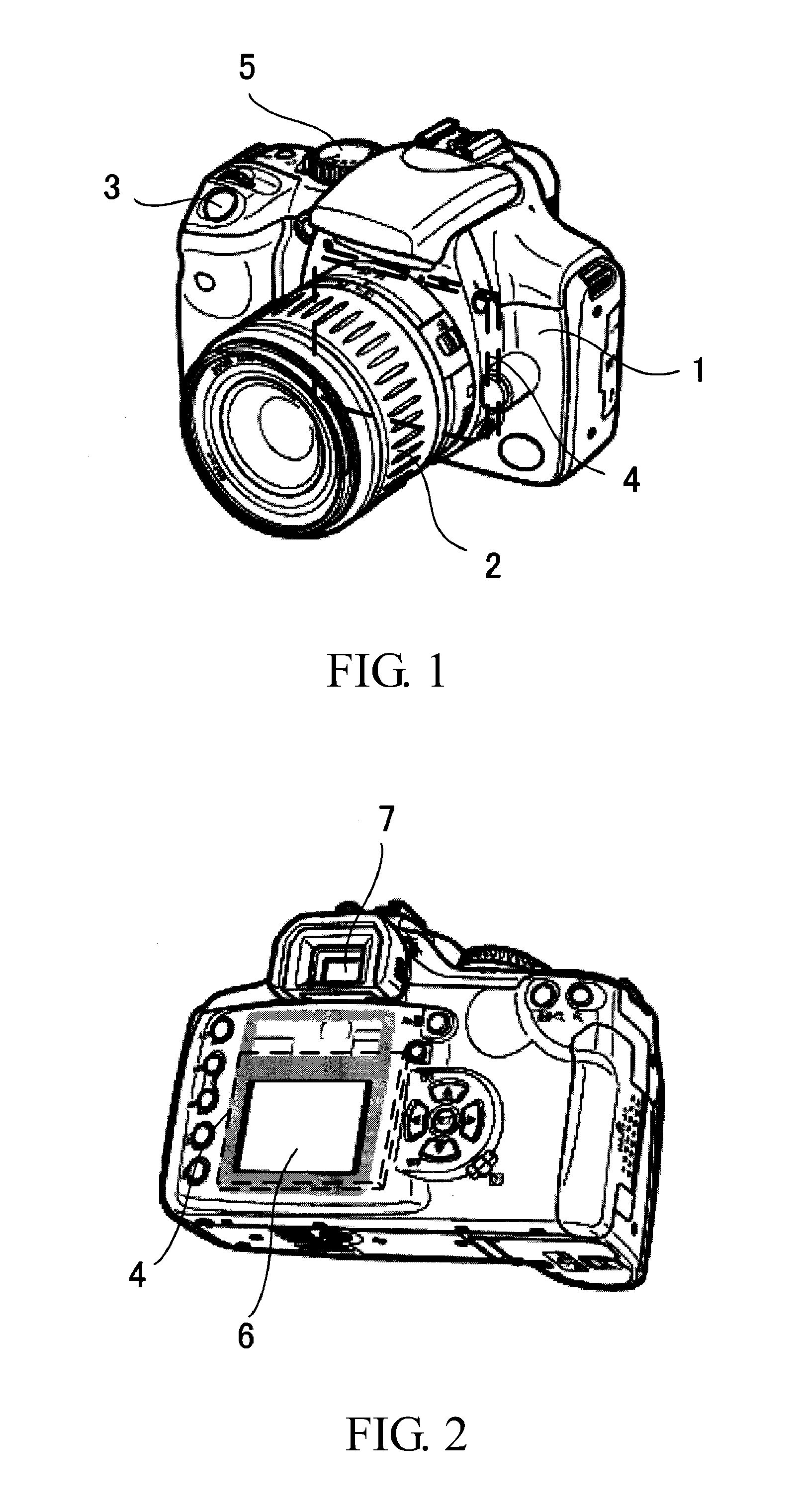
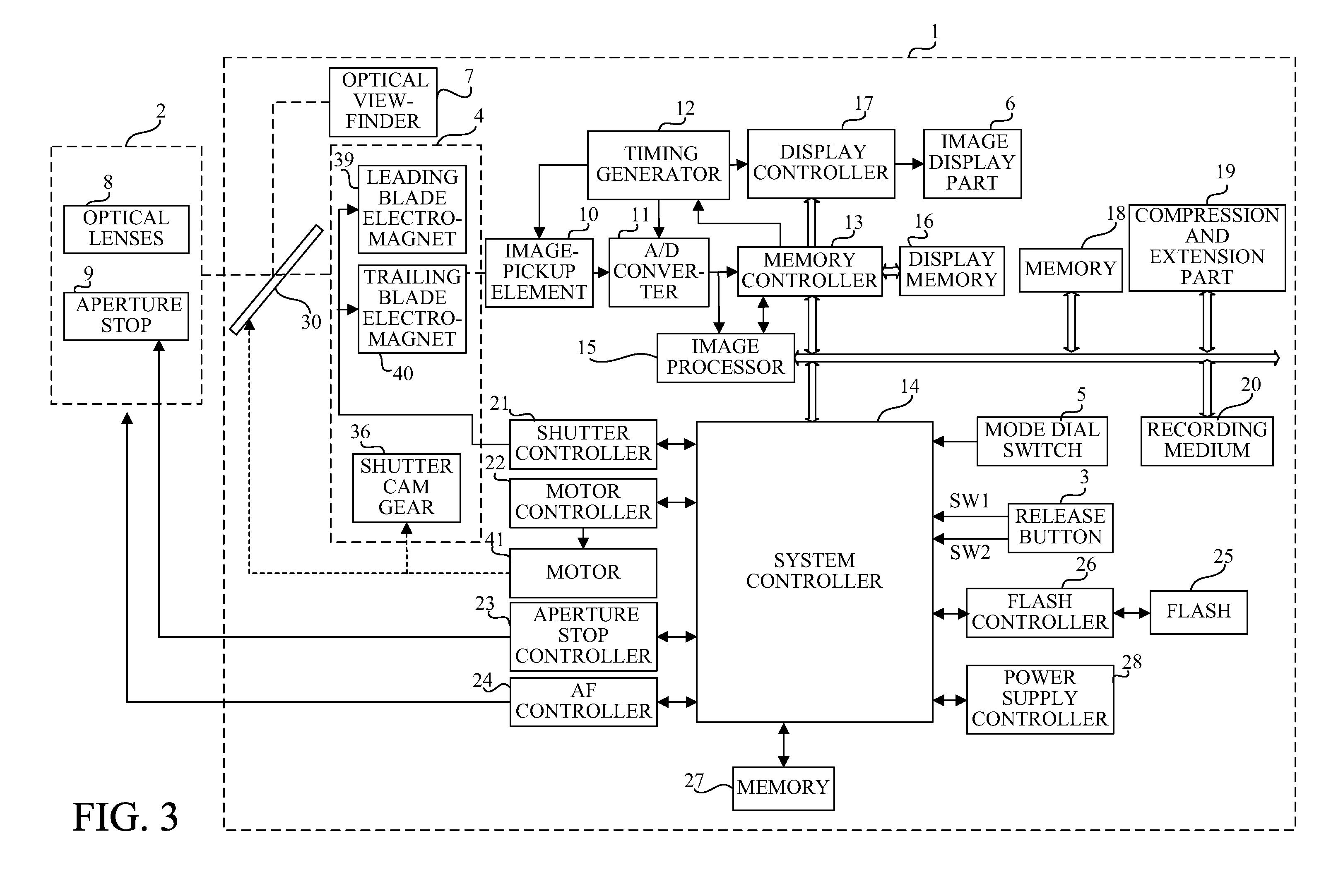
[0032]FIGS. 1 and 2 are respectively front and rear perspective views of a single-lens reflex digital camera (image pickup apparatus) provided with a focal-plane shutter apparatus that is a first embodiment (Embodiment 1) of the present invention.

[0033]Reference numeral 1 denotes the single-lens reflex digital camera (hereinafter simply referred to as the “camera”), and reference numeral 2 denotes an image-taking lens (interchangeable lens) detachably attached to the camera 1. Reference numeral 3 denotes a release button operable by a user. On the release button 3, a first stroke operation (that is, a half-push operation, and hereinafter referred to as “SW1ON”) to instruct start of photometry and AF (auto focus) and a second stroke operation (that is, a full-push operation, and hereinafter referred to as “SW2ON”) thereof to instruct image capturing (exposure) can be made.

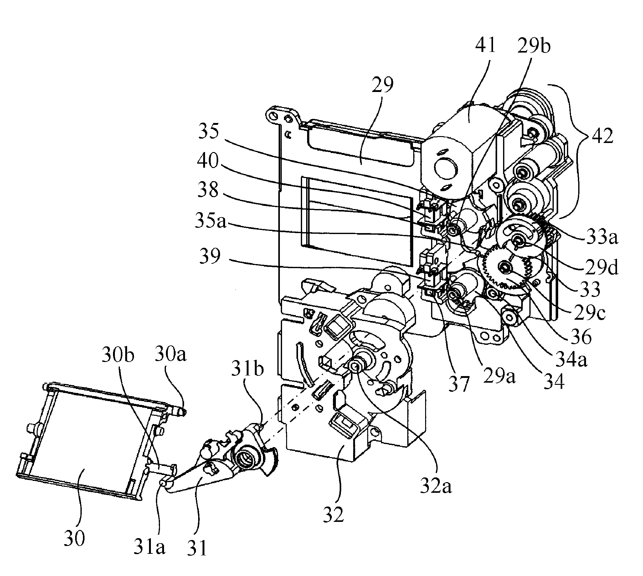
[0034]Reference numeral 4 denotes the focal-plane shutter apparatus (hereinafter simply referred to as the “shutt...

embodiment 2

[0107]Next, description will be made of a shutter that is a second embodiment (Embodiment 2) of the present invention with reference to FIGS. 14 and 15. FIG. 14 shows an overcharged state of the shutter, that is, a state where operations of the camera are stopped. Components in this embodiment common to those in Embodiment 1 are denoted by the same reference numerals as those in Embodiment 1, and descriptions thereof are omitted. Operations of the shutter 4 in this embodiment are identical to those of the shutter 4 shown in FIGS. 5, 7 to 10 and 12 in Embodiment 1, and descriptions thereof are omitted.

[0108]In this embodiment, on a shutter cam gear 36, a leading blade cam inclination portion 36b and a trailing blade cam inclination portion 36d are formed in angular areas having a same angle. In other words, in a rotation direction of the shutter cam gear 36, the angular area where the leading blade cam inclination portion 36b is formed on the shutter cam gear 36 and the angular area ...


PUM


Abstract

The focal-plane shutter apparatus includes a cam member and being rotated by a motor in one direction such that leading and trailing blade cams respectively make contact with leading and trailing blade driving members to drive them in a charging direction in which urging members are charged, and then to allow each of the leading and trailing blade driving members to move from a charge completion position to a blade drive standby position. Leading and trailing blade inclination portions of the cam member respectively allow each of the leading and trailing blade driving members to move from the charge completion position to the blade drive standby position. In a rotation direction of the cam member, a first angular area where the leading blade inclination portion is formed on the cam member is smaller than a second angular area where the trailing blade inclination portion is formed thereon.

Description

BACKGROUND OF THE INVENTION[0001]1. Field of the Invention[0002]The present invention relates to a focal-plane shutter apparatus provided in an image-pickup apparatus such as a single-lens reflex digital camera.[0003]2. Description of the Related Art[0004]Focal-plane shutter apparatuses include leading blade that are driven for exposure from a state of shutting a shutter aperture (hereinafter referred to as a “shut state”) to a state of opening the shutter aperture (hereinafter referred to as an “opened state”) and trailing blades that are driven for the exposure from the opened state to the shut state. The leading blades and the trailing blades are respectively constituted by plural light-blocking blades. The plural light-blocking blades are connected to each other by an arm member so as to form a parallel link, and thereby the light-blocking blades are parallel moved.[0005]The arm member is driven by a driving lever that is urged by a spring. The driving lever is provided with an ...

Claims


Application Information

Patent Timeline
IPC IPC(8): G03B9/08
CPCG03B9/20H04N2101/00H04N5/23245G03B19/12H04N23/667
Inventor NIWAMAE, YUUKI
Owner CANON KK
Features
  • Generate Ideas
  • Intellectual Property
  • Life Sciences
  • Materials
  • Tech Scout
  • Unparalleled Data Quality
  • Higher Quality Content
  • 60% Fewer Hallucinations
Learn More