Turbine blade

a turbine blade and turbine blade technology, applied in the field of turbine blades, can solve the problems of increasing the amount of cooling air, reducing the performance reducing the gas temperature of the gas turbine, so as to prevent low-temperature cooling air, reduce the total amount of cooling air (cooling air consumption), and reduce the cross-sectional area of the insert in the cavity

Active Publication Date: 2011-05-05
MITSUBISHI POWER LTD
View PDF9 Cites 11 Cited by
  • Summary
  • Abstract
  • Description
  • Claims
  • Application Information

AI Technical Summary

Benefits of technology

[0018]According to the turbine blade of the present invention, the flow passage cross-sectional areas of the inserts in the cavities are reduced, as shown in FIG. 3, for example; thus, the total amount of cooling air (cooling air consumption) can be reduced.
[0019]Further, part of cooling air introduced to the inside of an insert is blown out to the cooling space through the impingement cooling holes formed in the impingement plate and is used to impingement-cool the inner wall surface of the blade main body on the dorsal side and to film-cool the outer wall surface (outer circumferential surface) of the blade main body on the dorsal side; thus, it is possible to prevent low-temperature cooling air from being blown out through the film cooling holes.
[0020]A gas turbine according to the present invention includes a turbine blade capable of reducing the total amount of cooling air and of preventing low-temperature cooling air from being blown out through the film cooling holes.
[0021]According to the gas turbine of the present invention, the total amount of cooling air is reduced, thereby improving the performance of the gas turbine; and low-temperature cooling air is prevented from being blown out through the film cooling holes, thereby improving the heat efficiency of the gas turbine.
[0022]According to the present invention, an advantage is afforded in that it is possible to reduce the amount of cooling air (cooling medium) and to prevent low-temperature cooling air from being blown out through the film cooling holes.

Problems solved by technology

Therefore, there is a problem in that a flow passage cross-sectional area of the insert is inevitably increased, thus increasing the amount of cooling air and decreasing the performance of the gas turbine.
Therefore, there is a risk that low-temperature cooling air is blown out through the film cooling holes, thus reducing the gas temperature in the gas turbine and reducing the heat efficiency of the gas turbine.

Method used


Image

  • Turbine blade
  • Turbine blade
  • Turbine blade

Examples


Embodiment Construction

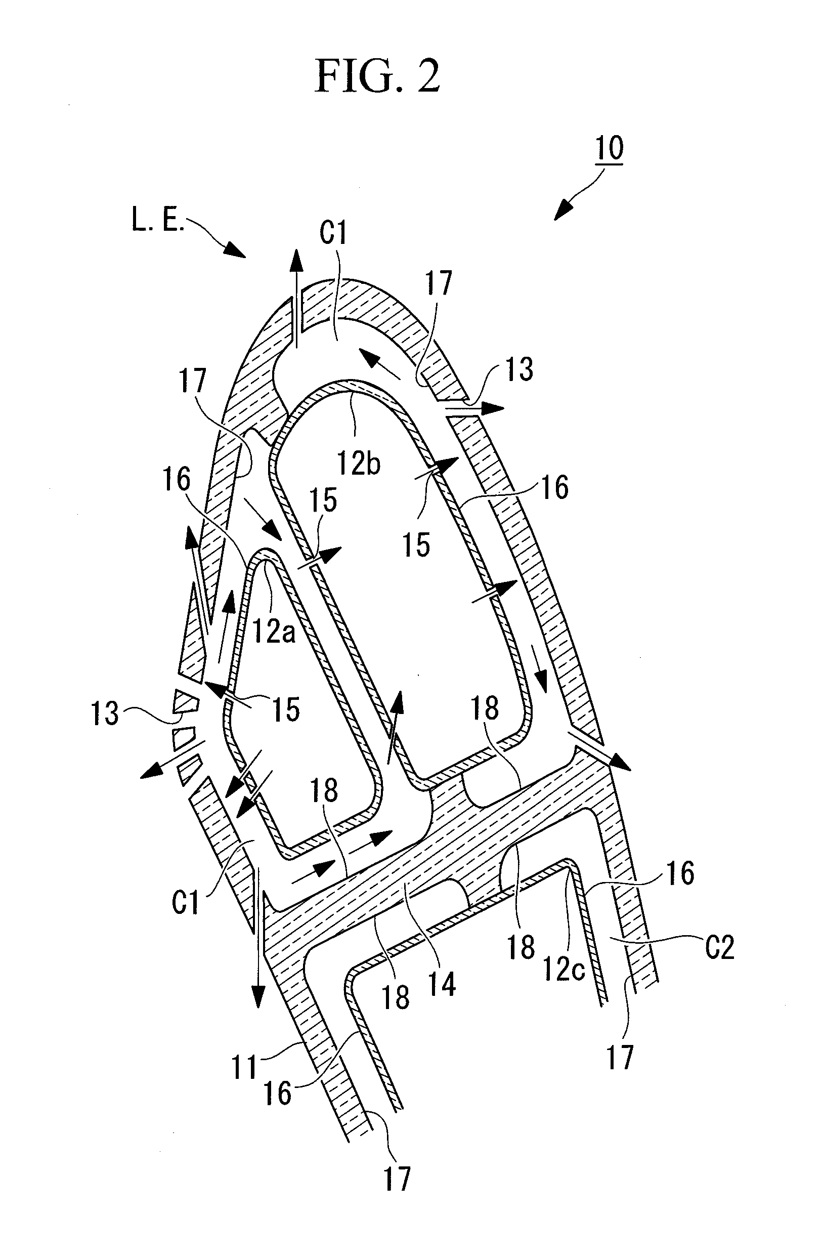
[0044]A turbine blade according to one embodiment of the present invention will be described below with reference to FIGS. 1 and 2.

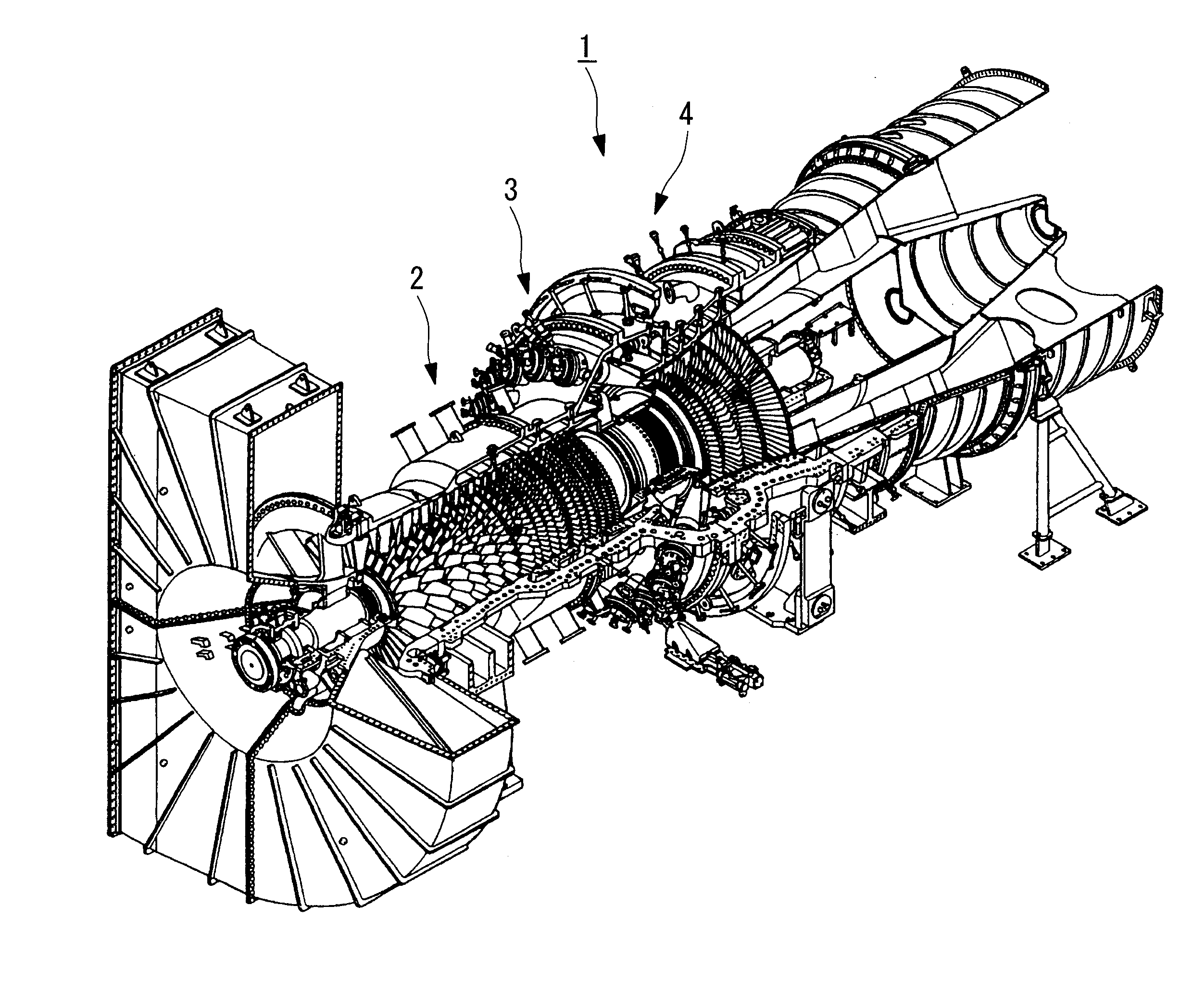
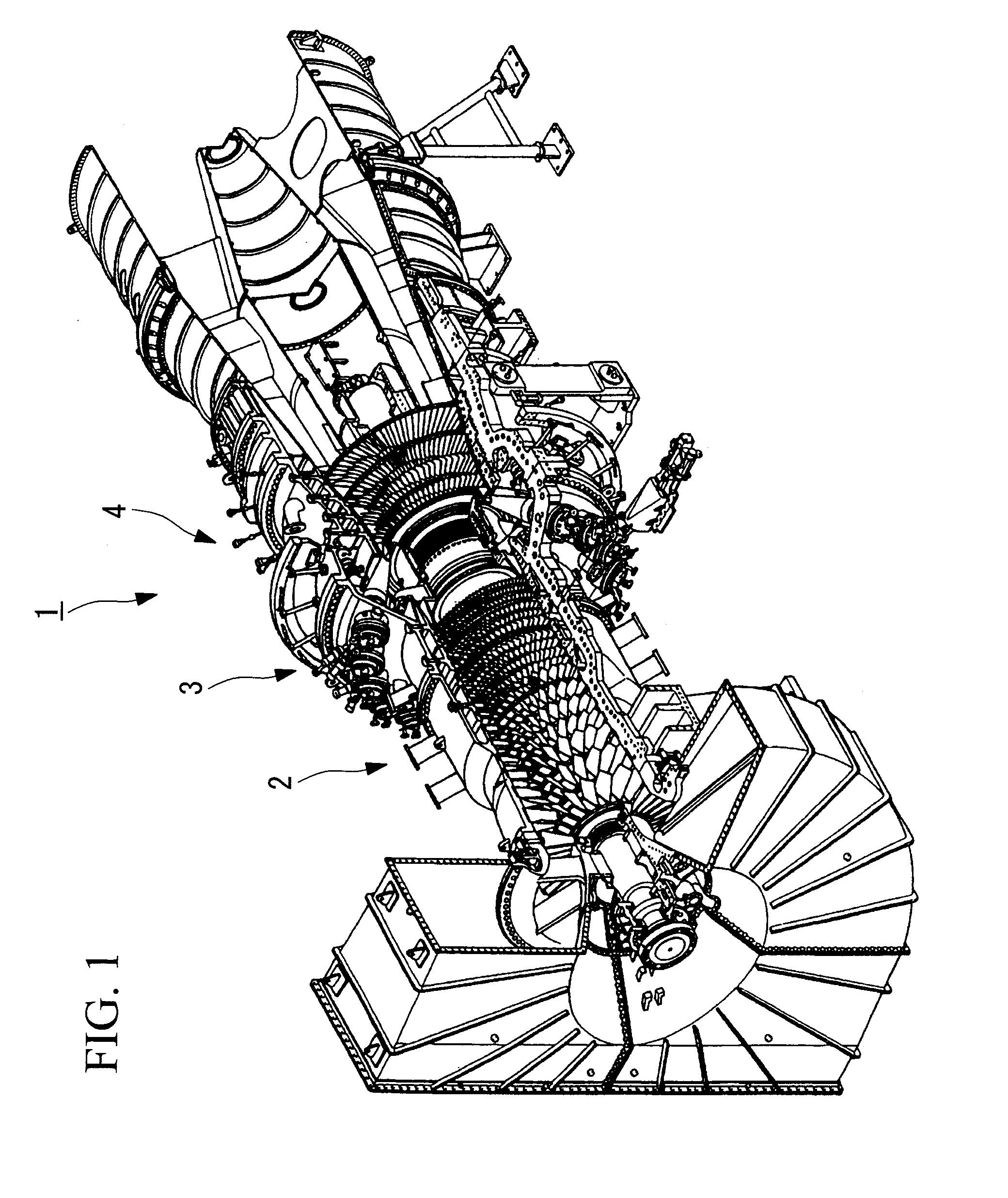
[0045]FIG. 1 is a view showing a gas turbine 1 having a turbine blade 10 according to the present invention and is a perspective view showing, in outline, a state where the upper half of a cylinder is removed. FIG. 2 is a main-portion sectional view of an approximately center portion of the turbine blade 10 according to this embodiment, in a plane substantially orthogonal to an upright-direction axis.

[0046]As shown in FIG. 1, the gas turbine 1 includes, as main components, a compression section 2 that compresses combustion air, a combustion section 3 that injects fuel into high-pressure air sent from the compression section 2 to combust it to produce high-temperature combustion gas, and a turbine section 4 that is located at a downstream side of the combustion section 3 and is driven by the combustion gas output from the combustion section 3.

[0047]As sho...


PUM


Abstract

The amount of cooling air (cooling medium) can be reduced, and low-temperature cooling air is prevented from being blown out through film cooling holes. Part of a cooling medium impingement-cooling an inner circumferential surface of a blade main body located on a ventral side further impingement-cools the inner circumferential surface of the blade main body located on a dorsal side and is blown out through film cooling holes in the blade main body that are located on the dorsal side.

Description

TECHNICAL FIELD[0001]The present invention relates to a gas turbine and, more specifically, to a turbine blade (rotor blade, stator blade) of the gas turbine.BACKGROUND ART[0002]A known example of a turbine blade (for example, a second-stage stator blade) in a turbine section of a gas turbine is disclosed in Patent Citation 1, for example.[0003]Patent Citation 1:[0004]Japanese Unexamined Patent Application, Publication No. Hei-3-253701DISCLOSURE OF INVENTION[0005]However, in a turbine blade disclosed in Patent Citation 1, in order to efficiently cool the inner wall surface (inner circumferential surface) of a blade main body, it is necessary to dispose the wall surface of an insert such that impingement holes therein are located as close as possible to the inner wall surface of the blade main body. Therefore, there is a problem in that a flow passage cross-sectional area of the insert is inevitably increased, thus increasing the amount of cooling air and decreasing the performance o...

Claims


Application Information

Patent Timeline
Patent Type & Authority Applications(United States)
IPC IPC(8): F01D5/18
CPCF01D5/189F05D2260/202F05D2260/201
Inventor HADA, SATOSHIHASHIMOTO, TOMOKOYURI, MASANORIKUWABARA, MASAMITSU
Owner MITSUBISHI POWER LTD
Why Eureka
Try Eureka