
Multiple Sprocket Assembly for a Bicycle

a bicycle and sprocket technology, applied in the direction of hoisting equipment, belt/chain/gearing, portable lifting, etc., can solve the problems of causing wear, and reducing the weight of the sprock

Active Publication Date: 2011-05-05
SRAM
View PDF9 Cites 55 Cited by
  • Summary
  • Abstract
  • Description
  • Claims
  • Application Information

AI Technical Summary

Benefits of technology

[0006]Another approach to minimize weight is disclosed in document DE 10 2008 010 904. The individual sprockets are formed as one piece from a single blank by turning and milling operations. This involves a gradation of number of teeth with larger differences in the number of teeth, as it given priority during use for a mountain bike. The support structure of the sprocket assembly forms a hollow element in the shape of a cone. The sprockets are not supported on a “spider” adapter relative to a driver on the rear wheel hub. Instead, the hollow cone element contacts and is supported driver at two positions axially spaced from each. The hollow cone element includes annular support elements having an annular cylinder and an annular disc. Openings between the annular support elements permit passage of dirt and sludge. Dirt accumulation beneath the chain engaging on the sprocket can be avoided by these openings. Otherwise the chain would force dirt patches on the sprocket inward and compress and consolidate them there. The consolidated dirt accumulations can increasingly grow in the radial direction and increasingly force the chain outward until the chain no longer properly engages on the sprocket teeth and finally jumps off. Despite its very low weight, the support structure is sufficiently rigid and solid so that interfering larger deformations and breaks as a result of the drive force of the chain may be avoided.

Problems solved by technology

The sprockets are highly loaded components and thus are subject to wear.
The sprockets are also subject to an undesirable bending load as a result of oblique chain tensile forces.
However, the achieved weight reduction is then limited.
One disadvantage of the above sprocket assembly is the high cost of manufacture by machining methods of turning and milling.

Method used


Image

  • Multiple Sprocket Assembly for a Bicycle
  • Multiple Sprocket Assembly for a Bicycle
  • Multiple Sprocket Assembly for a Bicycle

Examples


Embodiment Construction

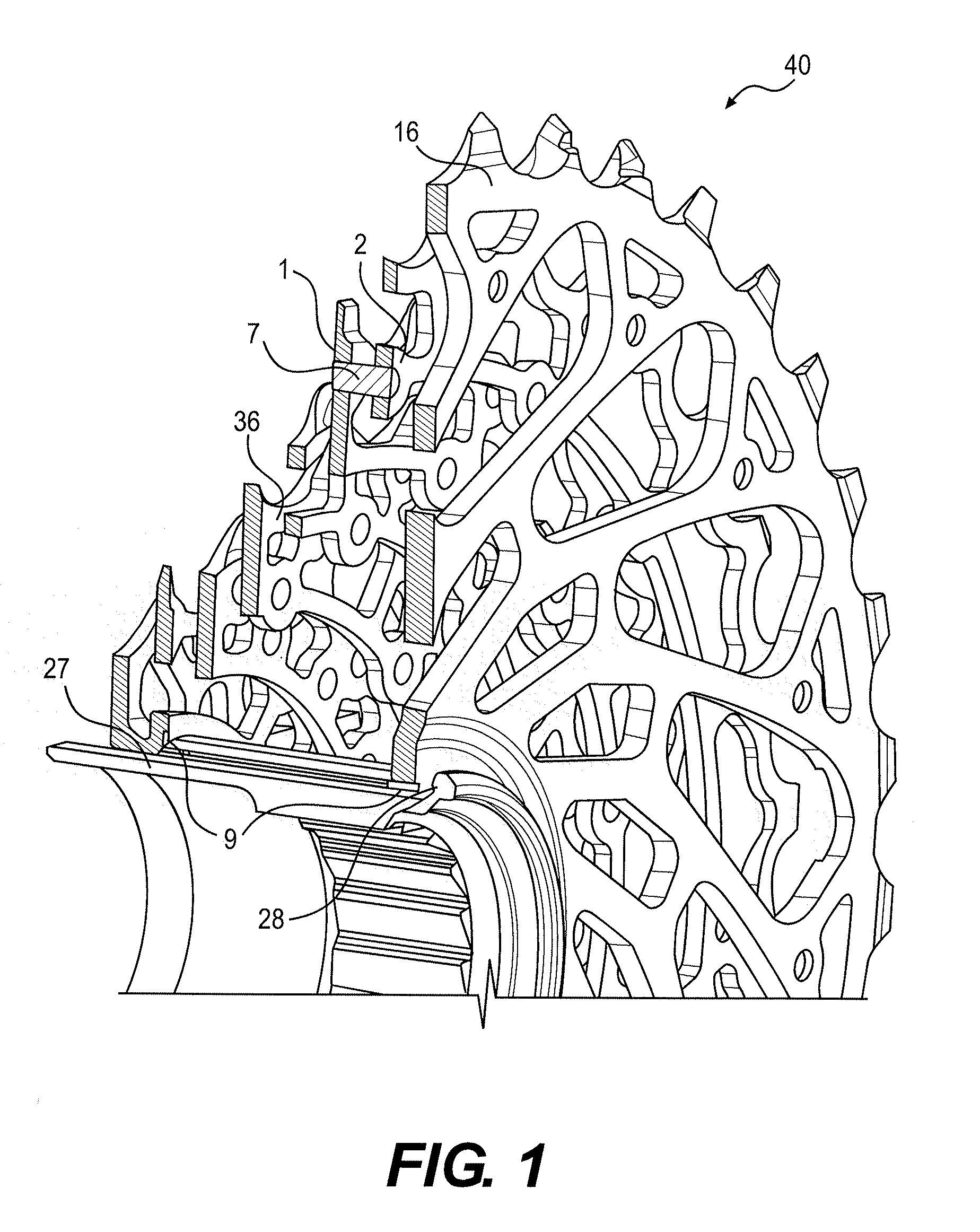
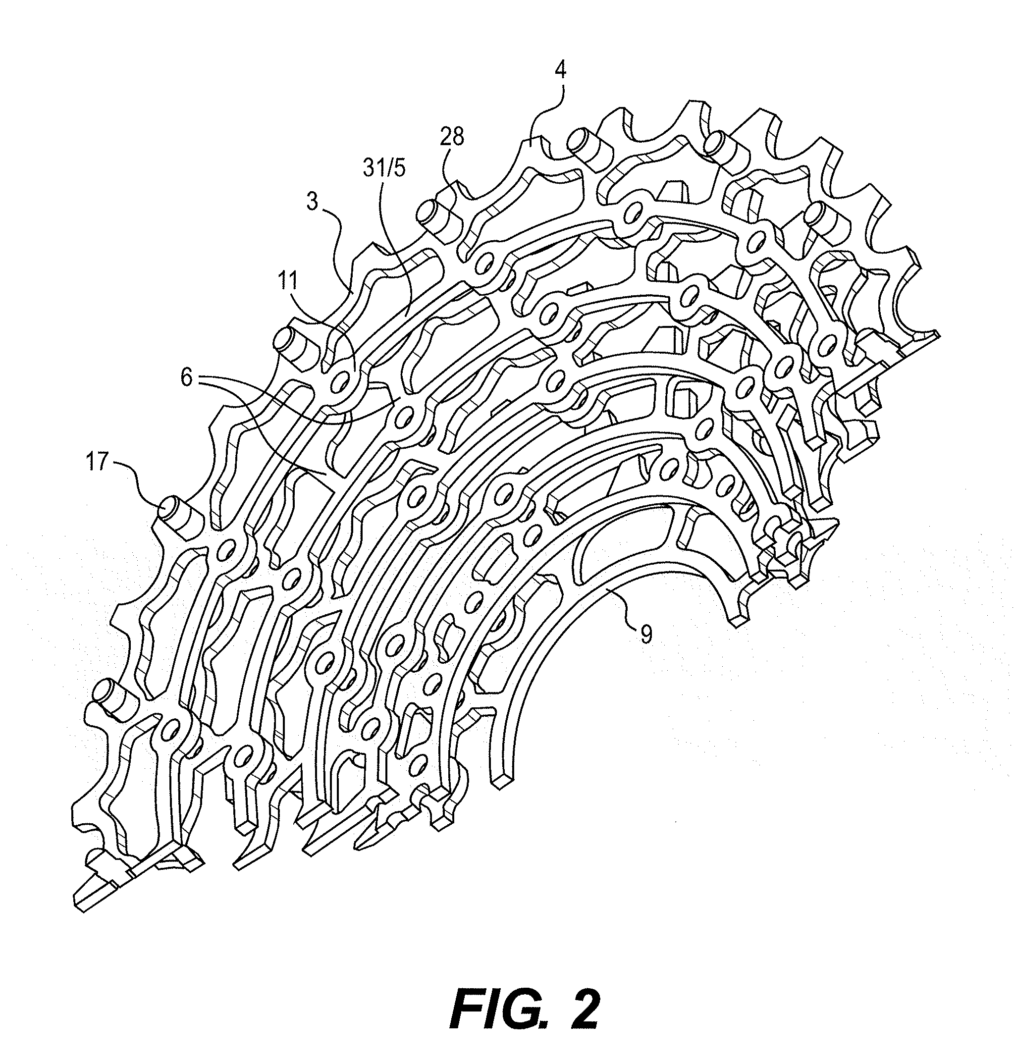
[0023]FIGS. 1-9 illustrate a multiple sprocket assembly according to one embodiment of the present invention. The multiple sprocket assembly may include a plurality of individual sprockets as shown in FIGS. 1 and 2. FIGS. 3-6, 8 and 9 show a smaller sprocket and / or a larger sprocket to more easily illustrate their relationship. The smaller and larger sprockets have substantially the same design. Sprockets can be viewed as a larger or smaller sprocket depending on the next smaller or larger sprocket additionally being considered.

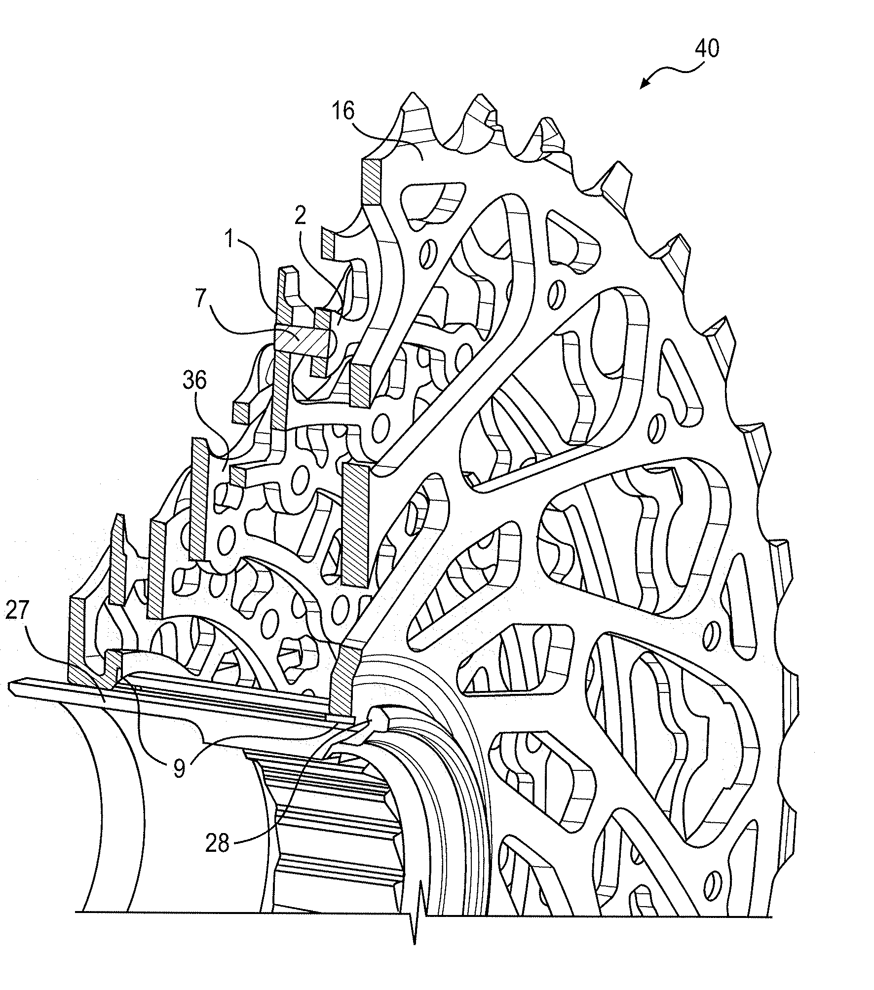
[0024]FIGS. 1 and 2 shows the multiple sprocket assembly 40 mounted on a driver 27 of a cassette hub in a longitudinal section along the axis of rotation. The multiple sprocket assembly 40 includes an end sprocket 16 having the largest number of teeth and having a different configuration than the other sprockets. The entire multiple sprocket assembly is supported on radial supports 9 extending radially from a rotational axis of driver 27 and sprockets 1, 2 on...


PUM


Abstract

A multiple sprocket assembly engageable with a roller chain and mountable to a driver of a rear wheel of a bicycle. The multiple sprocket assembly includes a smaller sprocket and a larger sprocket. Each of the smaller and larger sprockets has a radially outer ring with a plurality of teeth for engaging the roller chain. The radially outer ring has a plurality of radially outer pin mounts including a hole. The radially outer pin mounts are aligned with the teeth. The sprockets have a plurality of radially inner pin mounts connected to the radially outer ring forming a single piece. The radially inner pin mounts includes a hole. The radially inner pin mounts are aligned with the plurality of outer pin mounts disposed on an adjacent smaller sprocket. A plurality of pins connects the smaller sprocket and the larger sprocket to each other. The pins are mounted in the holes in the outer pin mounts on the smaller sprocket and in the holes in the inner, pin mounts of the larger sprocket. A first mounting sprocket is connected to the smaller sprocket by pins and a second mounting sprocket is connected to the larger sprocket by pins. The first and second mounting sprockets are supported on the hub axle at two positions spaced, apart in the axial direction of the hub axle.

Description

BACKGROUND OF THE INVENTION[0001]The present invention relates to multiple sprocket assemblies for bicycles, and more particularly, to a multiple sprocket assembly including a smaller sprocket and a larger sprocket connected by pins.[0002]A multiple sprocket assembly mounted to a rear wheel is one of the main components of a drive train for mountain and racing bikes. Multiple sprocket assemblies may include as many as eleven sprockets. The sprockets are highly loaded components and thus are subject to wear. Conventional sprockets have an inner contour with a torque-transmitting profile that is mountable to a driver of a cassette hub or to an outer ring of a freewheel hub. The spacing between adjacent sprockets is critical for shifting the bicycle chain from one sprocket to the adjacent sprocket and is determined by how the torque-transmitting profile on the sprockets engage the driver or the outer ring of the freewheel hub. The sprockets are also subject to an undesirable bending lo...

Claims


Application Information

Patent Timeline
IPC IPC(8): B62M9/10
CPCB62M9/10F16H55/303
Inventor BRAEDT, HENRIK
Owner SRAM
Learn More