Self-Pivoting Spinal Implant and Associated Instrumentation

Active Publication Date: 2011-05-05
DEPUY SYNTHES PROD INC
View PDF78 Cites 103 Cited by
  • Summary
  • Abstract
  • Description
  • Claims
  • Application Information

AI Technical Summary

Benefits of technology

[0008]Yet another embodiment of the present invention comprises a system for spine surgery at a disc space disposed between first and second endplates of adjacent vertebral bodies of a patient. The system includes an intervertebral implant including an insertion end and an opposing engagement end. First and second opposed main surfaces are configured to contact respective adjacent vertebral endplates. Each of the first and second main surfaces has an anterior edge, a posterior edge, and extends between the insertion and engagement ends. An anterior wall is formed between the first and second main surfaces and along the anterior edges thereof. A posterior wall is formed between the first and second main surfaces and along the posterior edges thereof. The anterior wall and the posterior wall converge at the insertion and engagement ends. A slot is formed at the engagement end and extends continuously between and at least partially along the anterior and posterior walls. A post is positioned within the slot, spaced from at least one of the anterior and posterior walls and extending at least partially between the first and second main surfaces. The post includes a plurality of exposed facets. A trial implant includes an insertion end and an opposing engagement end. First and second opposed main surfaces are configured to contact respective adjacent vertebral endplates. Each of the first and second main surfaces has an anterior edge, a posterior edge, and extends between the insertion and engagement ends. An anterior wall is formed between the first and second main surfaces and along the anterior edges thereof. A posterior wall is formed between the first and second main surfaces and along the posterior edges thereof. The anterior wall and the posterior wall converge at the insertion and engagement ends. A slot is formed at the engagement end and extends continuously between and at lea

Problems solved by technology

The unilateral transforaminal insertion of an interbody spacer for lumbar spinal fusion presents challenges to the surgeon tasked with the procedure due to the curved manipulation path that the implant must undergo once it enters the disc space.
The procedure presents a further challenge of coupling the implant to the inserter instrument while allowing the implant a limited amount of rotation or articulation to follow the desired path.
These challenges also pr

Method used


Image

  • Self-Pivoting Spinal Implant and Associated Instrumentation
  • Self-Pivoting Spinal Implant and Associated Instrumentation
  • Self-Pivoting Spinal Implant and Associated Instrumentation

Examples


Example

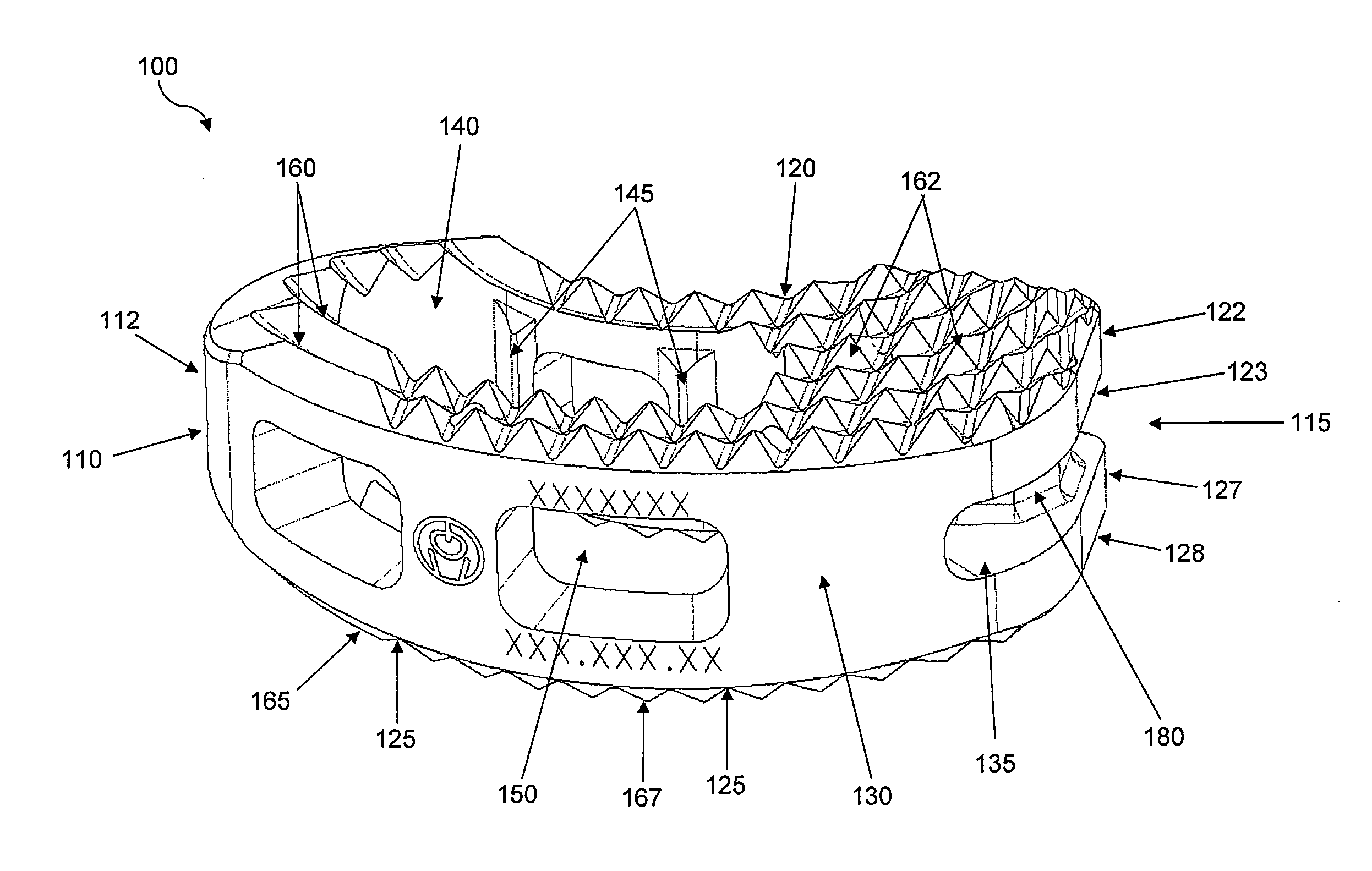
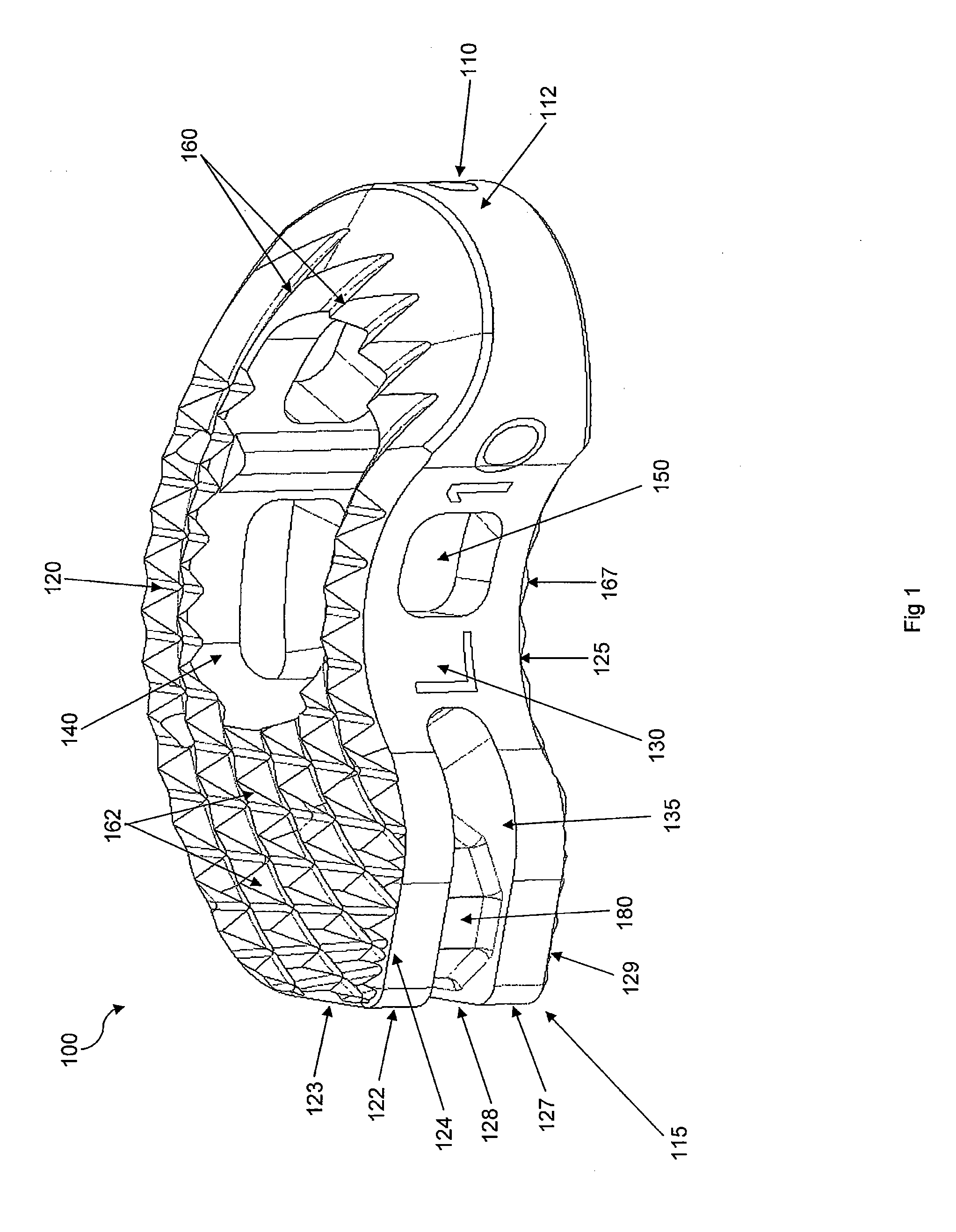
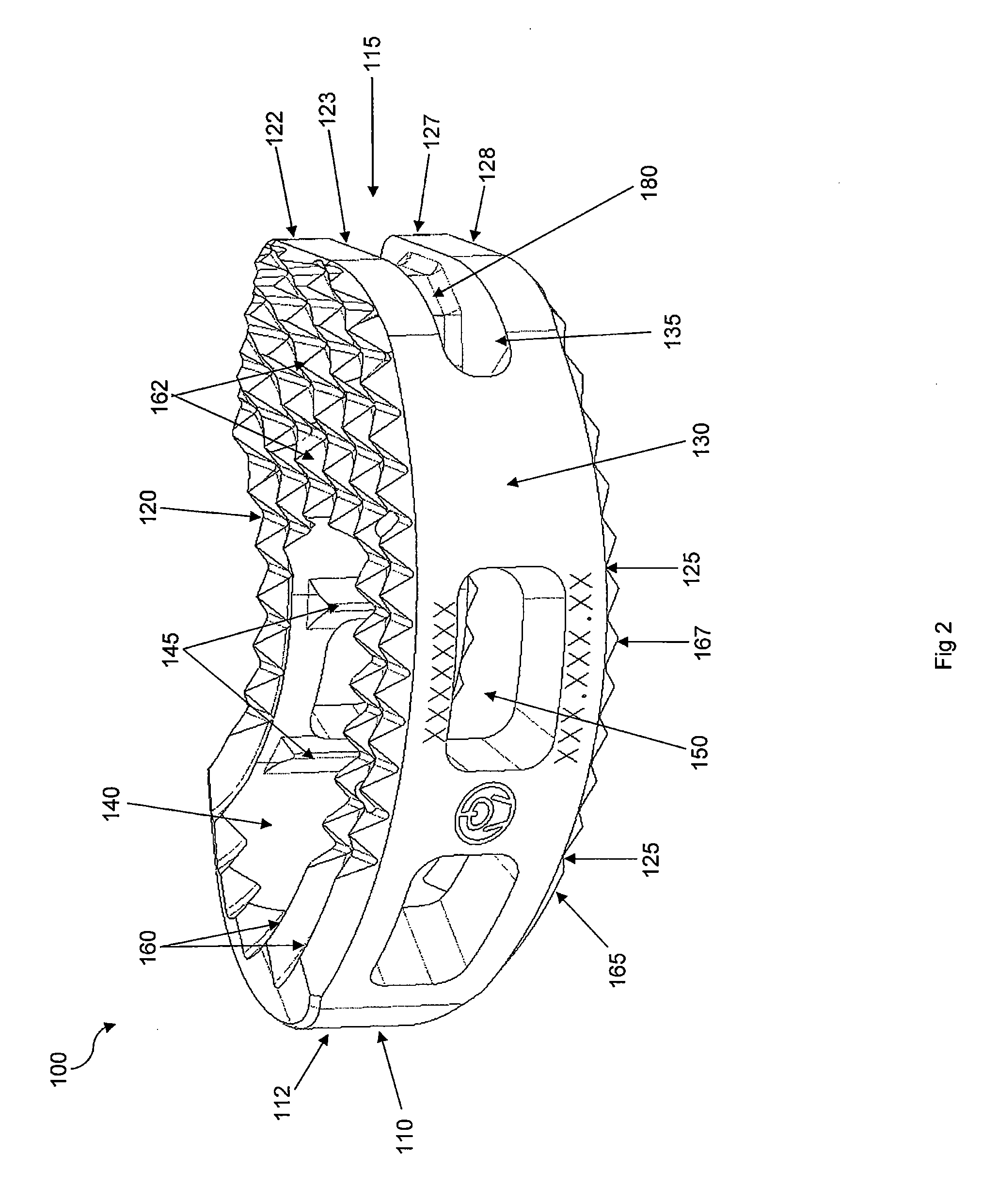
[0034]Certain terminology is used in the following description for convenience only and is not limiting. The words “right,”“left,”“lower,” and “upper” designate directions in the drawings to which reference is made. The words “inwardly” or “distally” and “outwardly” or “proximally” refer to directions toward and away from, respectively, the patient's body, or the geometric center of the interbody spacer implant and related parts thereof. The words, “anterior,”“posterior,”“superior,”“inferior,” and related words and / or phrases designate preferred positions and orientations in the human body to which reference is made and are not meant to be limiting. The terminology includes the above-listed words, derivatives thereof and words of similar import.

[0035]Referring to FIGS. 1-6, a TLIF spacer 100 is provided that includes an insertion end 110 and an engagement end 115, the insertion end 110 preferably forming a bullet-nose 112 or having some other tapered geometry for enhancing the ease ...


PUM


Abstract

An intervertebral implant includes an insertion end, an opposing engagement end, and first and second opposed main surfaces configured to contact respective adjacent vertebral endplates. Each of the first and second main surfaces has an anterior edge, a posterior edge, and extends between the insertion and engagement ends. Anterior and posterior walls are formed between the first and second main surfaces and along the respective anterior and posterior edges and converge at the insertion and engagement ends. A slot is formed at the engagement end and extends continuously between and at least partially along the anterior and posterior walls. A post is positioned within the slot, spaced from at least one of the anterior and posterior walls and extending at least partially between the first and second main surfaces. The post includes a plurality of exposed facets and is configured for engagement with a pivotable insertion instrument.

Description

BACKGROUND OF THE INVENTION[0001]The unilateral transforaminal insertion of an interbody spacer for lumbar spinal fusion presents challenges to the surgeon tasked with the procedure due to the curved manipulation path that the implant must undergo once it enters the disc space. The procedure presents a further challenge of coupling the implant to the inserter instrument while allowing the implant a limited amount of rotation or articulation to follow the desired path. These challenges also present themselves to other angular unilateral approaches to the spine, in which the initial access corridor is linear yet, once the implant enters the disc space, the implant must be manipulated or articulated along a curved path. Conventional transforaminal lateral interbody fusion (TLIF) implants, for example, are inserted using a combination of a linear insertion path and a hammering of the implant into the desired position using pushers that provide the desired anterior positioning of the imp...

Claims


Application Information

Patent Timeline
IPC IPC(8): A61F2/44
CPCA61F2/4465A61F2310/00023A61F2/4684A61F2002/2835A61F2002/3008A61F2002/30378A61F2002/30383A61F2002/30538A61F2002/30594A61F2002/30604A61F2002/30616A61F2002/30772A61F2002/3082A61F2002/30841A61F2002/30843A61F2002/30879A61F2002/30892A61F2002/4475A61F2002/4622A61F2002/4627A61F2002/4628A61F2310/00017A61F2/4611A61F2220/0016A61F2250/0098A61F2310/00047A61F2310/00095A61F2310/00131A61F2002/30593A61F2/4603
Inventor LINDENMANN, PHILIPPESAIDHA, SEANBAUDOUIN, CYRILFATONE, PETER
Owner DEPUY SYNTHES PROD INC
Why Eureka
Try Eureka