Nanopore device and a method for nucleic acid analysis

Active Publication Date: 2011-05-12
OXFORD NANOPORE TECH LTD
View PDF6 Cites 9 Cited by
  • Summary
  • Abstract
  • Description
  • Claims
  • Application Information

AI Technical Summary

Benefits of technology

[0064]Biological pores have proved useful for a range of experiments but exhibit some disadvantages such as fixed size and limited stability. External factors, such as temperature and

Problems solved by technology

In certain instances, such as with biopsy samples, it is very disadvantageous if the sample must be split in two halves in order to run two differen

Method used


Image

  • Nanopore device and a method for nucleic acid analysis
  • Nanopore device and a method for nucleic acid analysis
  • Nanopore device and a method for nucleic acid analysis

Examples


Embodiment Construction

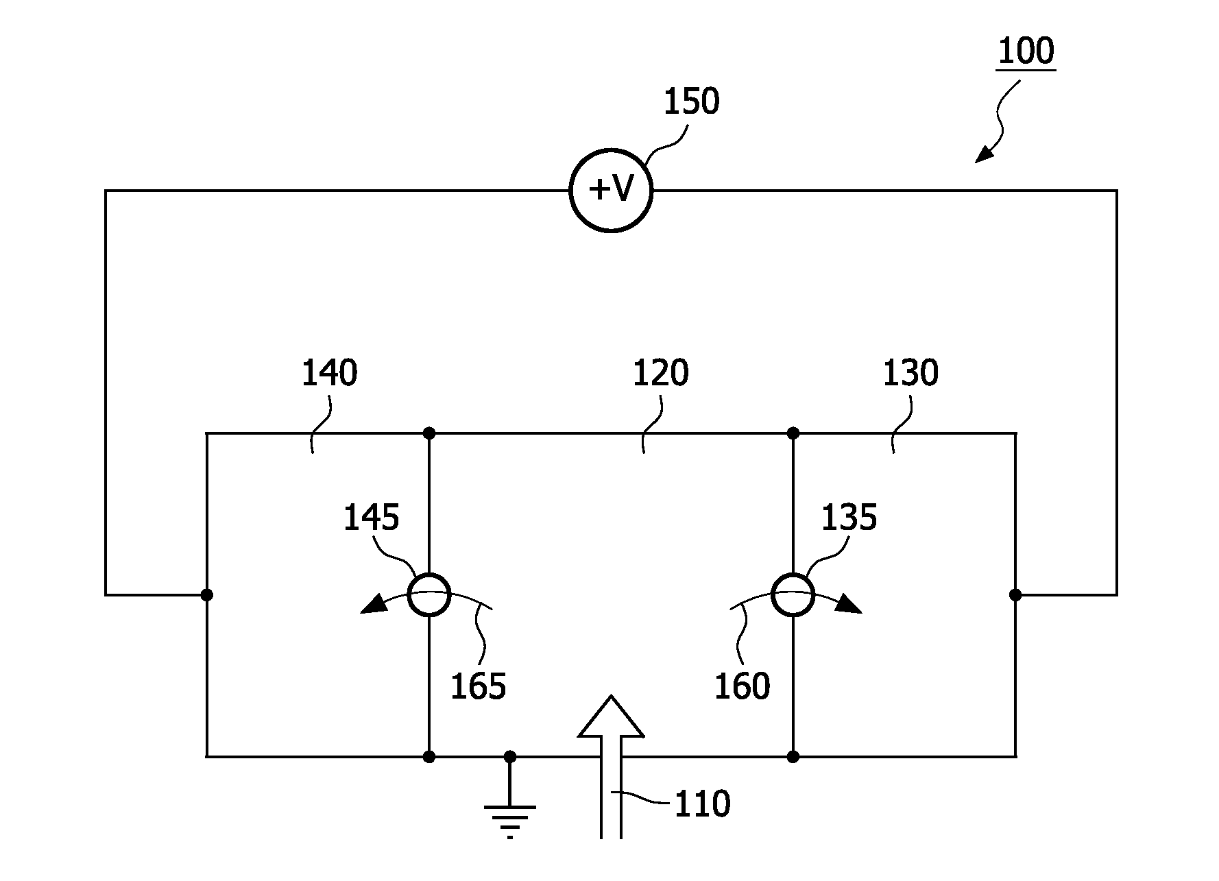
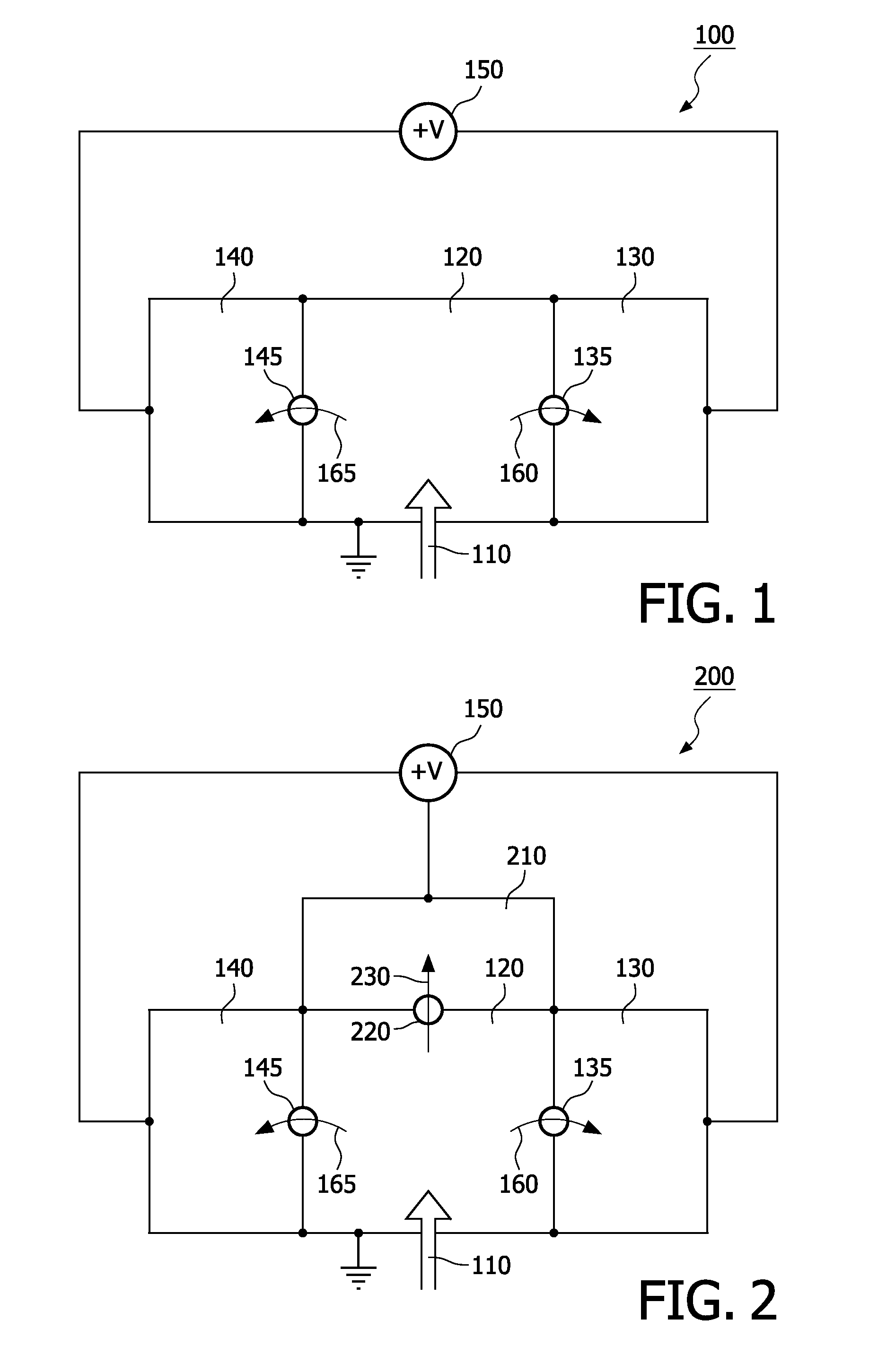
[0082]FIG. 1 depicts a nanopore device 100 according to the invention. The device comprises a sample input 110 for inputting a sample of nucleic acid material (not shown), such as DNA, RNA or uRNA, which is prepared into small fragments (not shown), into an input chamber 120. For DNA these small fragments have a negative electric charge. The input chamber 120 is arranged to be connected to a first sample chamber 130 via a first nanopore 135 and to a second sample chamber 140 via a second nanopore 145. The nanopores 135, 145 further comprise specific detection molecules (not shown) which are tailored to the required detection function of the nanopore. An electrolytic solution (not shown) is present in the chambers 120, 130, 140 and comprises charged particles. Means to apply an electrical potential difference 150 are arranged so that an electrical potential difference is present across both nanopores 135, 145. (This means to apply an electrical potential difference is shown here as i...


PUM

PropertyMeasurementUnit
Currentaaaaaaaaaa

Abstract

A nanopore device is described wherein is provided a sample input (110), an input chamber (120), and first and second sample chambers (130, 140) connected to the input chambers (120) via first and second nanopores (135, 145).

Description

FIELD OF THE INVENTION[0001]The invention relates to the field of determining information from nucleic acid material, for example genetic material such as DNA. In particular, the invention relates to the field of rapid nucleic acid analysis by means of a nanopore device.[0002]Specifically the invention relates to a nanopore device, arranged to cooperate with a sample of genetic material, the nanopore device comprising[0003]an input chamber, for containment of the sample of nucleic acid[0004]a first chamber connected to the input chamber by a first nanopore[0005]means to apply an electrical potential difference across the first nanopore, the electrical potential being arranged to draw a first fragment of the sample of genetic material through the first nanopore[0006]an electrolytic solution which is capable of flow through the first nanopore under the influence of the electrical potential difference, the flow detectable as a first ionic current, changes in the first ionic current bei...

Claims


Application Information

Patent Timeline
IPC IPC(8): G01N27/447H05K13/00B82Y5/00
CPCG01N33/48721Y10T29/49002
Inventor VAN DER ZAAG, PIETER JANVAN DE STOLPE, ANJAMCCOO, ELAINEVAN WANROOIJ, EVA VAN
Owner OXFORD NANOPORE TECH LTD
Why Eureka
Try Eureka