Capacitive Touch Screen Panel

a touchscreen panel and capacitive technology, applied in the field of capacitive touchscreen panel, can solve the problems of initial malfunctions, damage, and the touch screen may operate irrespectively, and achieve the effects of reducing the fabrication cost of the touch screen, preventing malfunctions and damage, and preventing malfunctions from occurring

Inactive Publication Date: 2011-05-12
E&H
View PDF11 Cites 66 Cited by
  • Summary
  • Abstract
  • Description
  • Claims
  • Application Information

AI Technical Summary

Benefits of technology

[0012]The present invention is directed to a capacitive touch-screen panel capable of preventing malfunctions from occurring due to a state of contact with an upper portion of an electrode unit of a touch screen, preventing malfunctions and damage from occurring due to scratches and static electricity during a contact with the touch screen, effectively reducing fabrication costs of the touch screen, and greatly simplifying the entire process of fabricating the touch-screen panel.

Problems solved by technology

However, when contacting an electrode unit of the above-described conventional touch screen, the touch screen may operate irrespective of a user's intentions due to degradation in linearity at the electrode unit.
Furthermore, even when a protection layer is formed on the top surface of the conductive light transmission plate to prevent scratch damages, the protection layer is formed of a simple synthetic resin so that a user cannot appropriately cope with static electricity applied during a contact of the user with the capacitive touch screen, thus causing initial malfunctions and damage.

Method used


Image

  • Capacitive Touch Screen Panel
  • Capacitive Touch Screen Panel
  • Capacitive Touch Screen Panel

Examples


embodiment 1

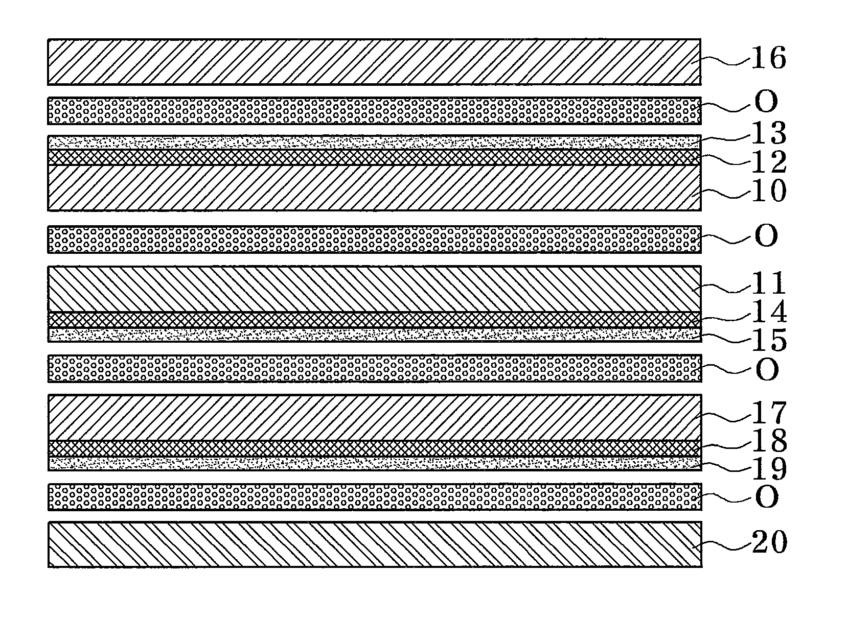
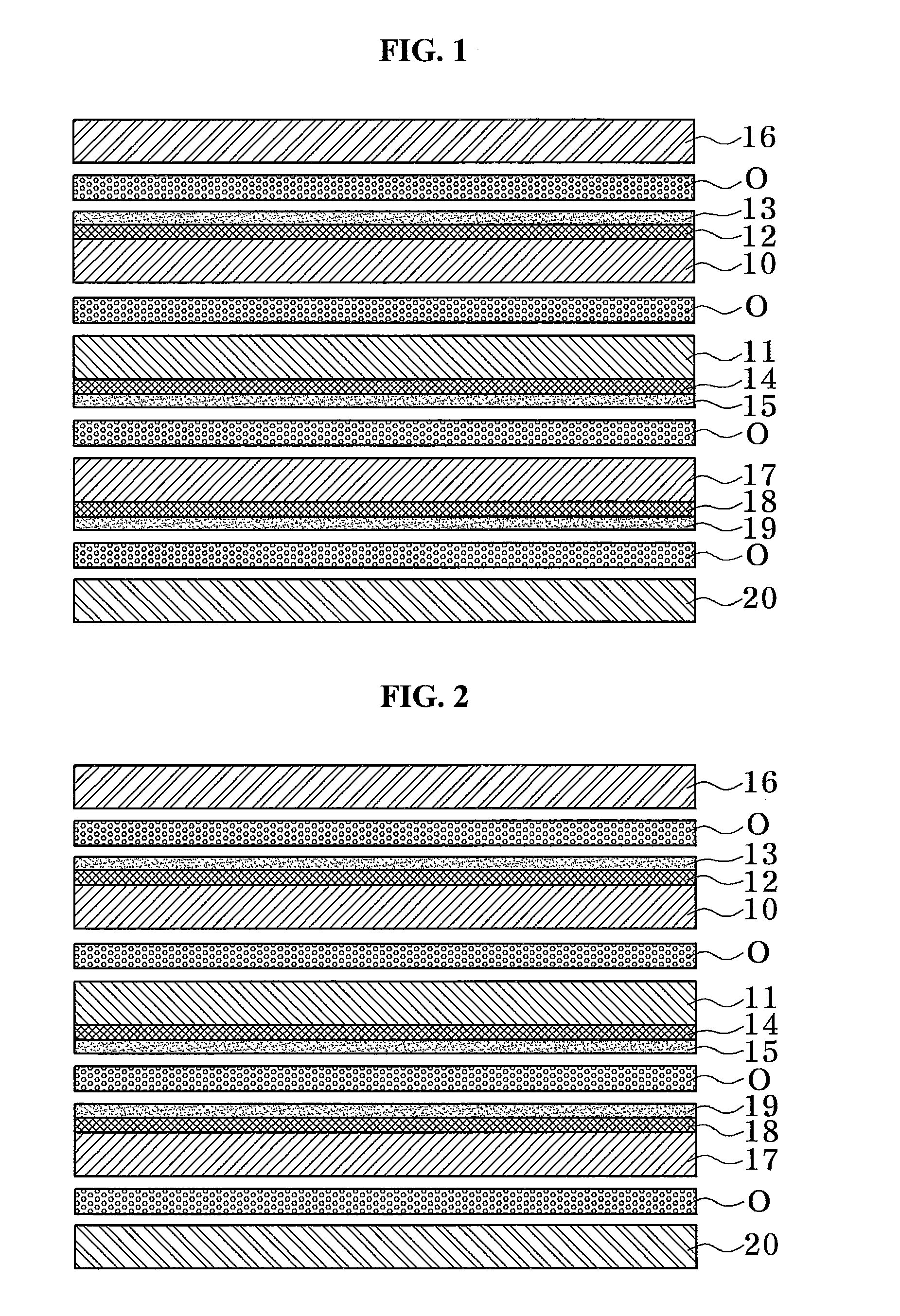
[0059]FIG. 5 is a plan view of a capacitive touch-screen panel according to a first exemplary embodiment of the present invention, FIGS. 6 and 7 are plan views of only first and second substrates of FIG. 5, respectively, FIG. 8 is a longitudinal sectional view of a capacitive touch-screen panel according to a first exemplary embodiment of the present invention, and FIG. 9 is a cross-sectional view taken along line A-A′ of FIG. 5.

[0060]Referring to FIGS. 5 through 9, a capacitive touch-screen panel may include first and second substrates 100 and 110, first and second transparent electrode panel units 120 and 130, and first and second outer electrode interconnections 140 and 150.

[0061]First lateral surfaces of the first and second substrates 100 and 110 may be bonded with each other by an interlayer adhesive O. Each of the first and second substrates 100 and 110 may include a screen region S and an inactive region X.

[0062]Each of the first and second substrates 100 and 110 may be a tr...

embodiment 2

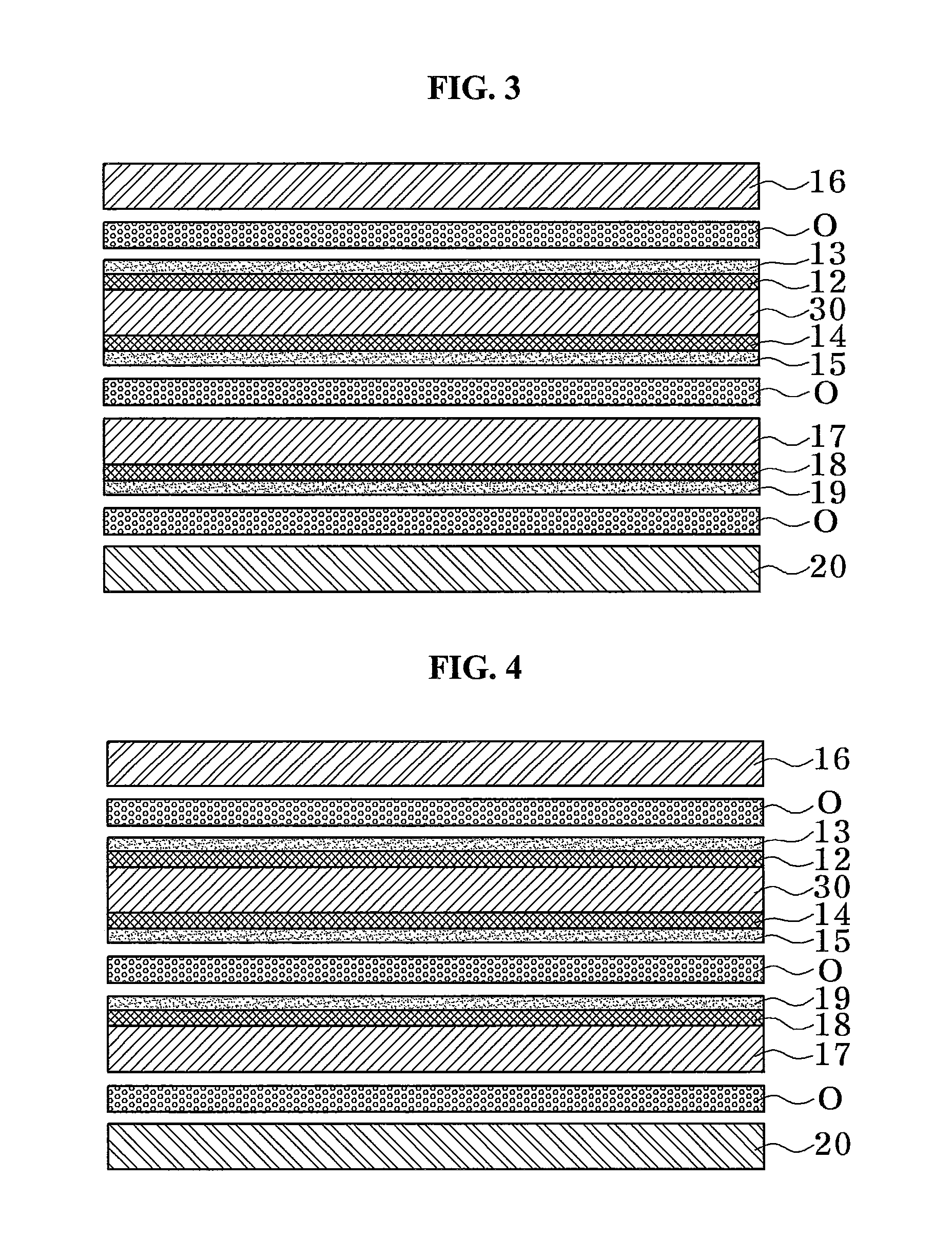
[0072]FIG. 10 is a plan view of a capacitive touch-screen panel according to a second exemplary embodiment of the present invention, FIGS. 11 and 12 are plan views of only first and second substrates of FIG. 10, respectively, FIG. 13 is a longitudinal sectional view of a capacitive touch-screen panel according to a second exemplary embodiment of the present invention, and FIG. 14 is a cross-sectional view taken along line B-B′ of FIG. 10.

[0073]Referring to FIGS. 10 through 14, a capacitive touch-screen panel according to a second exemplary embodiment of the present invention may include first and second substrates 200 and 210, first and second transparent electrode pattern units 220 and 230, and first and second outer electrode interconnections 240 and 250.

[0074]Since the first and second substrates 200 and 210 and the first and second transparent electrode pattern units 220 and 230 are the same as in the previously described first exemplary embodiment, a detailed description thereo...


PUM


Abstract

Provided is a capacitive touch-screen panel. The capacitive touch-screen panel includes a first substrate having a screen region and an inactive region, a first transparent electrode pattern unit disposed in the screen region of a first lateral surface of the first substrate, a first outer electrode interconnection formed in the inactive region of the first lateral surface of the first substrate and electrically connected to the first transparent electrode pattern unit, a second substrate having a first lateral surface bonded with a second lateral surface of the first substrate using an interlayer adhesive, the second substrate having a screen region and an inactive region, a second transparent electrode pattern unit disposed on the screen region of a second lateral surface of the second substrate, and a second outer electrode interconnection formed in the inactive region of a second lateral surface of the second substrate and electrically connected to the second transparent electrode pattern unit. The capacitive touch-screen panel is configured to sense a touched position with a variation in capacitance due to a contact with the first and second transparent electrode pattern units. As a result, malfunctions from occurring due to a state of contact with an upper portion of an electrode unit of a touch screen and malfunctions and damage from occurring due to scratches and static electricity during a contact with the touch screen may be prevented. Further, the fabrication cost of a touch screen may be efficiently reduced, and the fabrication process of a touch-screen panel may be greatly simplified.

Description

CROSS-REFERENCE TO RELATED APPLICATION[0001]This application claims priority to and the benefit of Korean Patent Application No. 2009-14912, filed on Feb. 23, 2009, the disclosure of which is incorporated herein by reference in its entirety.BACKGROUND[0002]1. Field of the Invention[0003]The present invention relates to a capacitive touch-screen panel, and more particularly, to a capacitive touch-screen panel capable of preventing malfunctions from occurring due to a state of contact with an upper portion of an electrode unit of a touch screen, preventing malfunctions and damage from occurring due to scratches and static electricity during a contact with the touch screen, effectively reducing fabrication costs of the touch screen, and greatly simplifying the entire process of fabricating the touch-screen panel.[0004]2. Discussion of Related Art[0005]In general, a touch screen is an input apparatus that allows all types of people to dialogically and intuitively manipulate a computer u...

Claims


Application Information

Patent Timeline
Patent Type & Authority Applications(United States)
IPC IPC(8): G06F3/045
CPCG06F3/044G06F2203/04103G06F3/04164G06F3/0445G06F3/0446G06F3/0412G06F2203/04111G06F2203/04112G06F3/04182
Inventor LEE, YONG HOON
Owner E&H
Why Eureka
Try Eureka