Display device, method of driving the same, and electronic unit

Inactive Publication Date: 2011-05-12
SONY CORP
View PDF15 Cites 4 Cited by
  • Summary
  • Abstract
  • Description
  • Claims
  • Application Information

AI Technical Summary

Benefits of technology

[0010]At present, in the market of flat panel displays, the share of a liquid crystal television using a liquid crystal display device is increasing. A lower price as well as a larger and thinne

Problems solved by technology

However, in the case of simply reducing the number of output

Method used


Image

  • Display device, method of driving the same, and electronic unit
  • Display device, method of driving the same, and electronic unit
  • Display device, method of driving the same, and electronic unit

Examples


first embodiment (

2. First embodiment (example of switching from on-voltage of scan line voltage to off-voltage at the time of applying gray-scale interpolation voltage within a basic voltage writing period)

second embodiment (

3. Second embodiment (example of setting the gray-scale interpolation voltage to a voltage value lower than the basic voltage)

4. Third embodiment (example of varying the scan line voltage over three values (Von1, Von2, and Voff), using the voltage Von1 at the time of applying the video signal voltage, and using the voltage Von2 (1) at the time of applying the gray-scale interpolation voltage)

5. Fourth embodiment (example of varying power supply voltage over three values (Vcc1, Vcc2, and Vini), using the voltage Vcc1 at the time of applying the video signal voltage, and using the voltage Vcc2 (1) at the time of applying the gray-scale interpolation voltage

fifth embodiment (

6. Fifth embodiment (example of performing D / A conversion while setting a dynamic range of the gray-scale interpolation voltage to be smaller than that of the video signal voltage)

7. Module and application examples

[0057]Configuration of Display Device 1

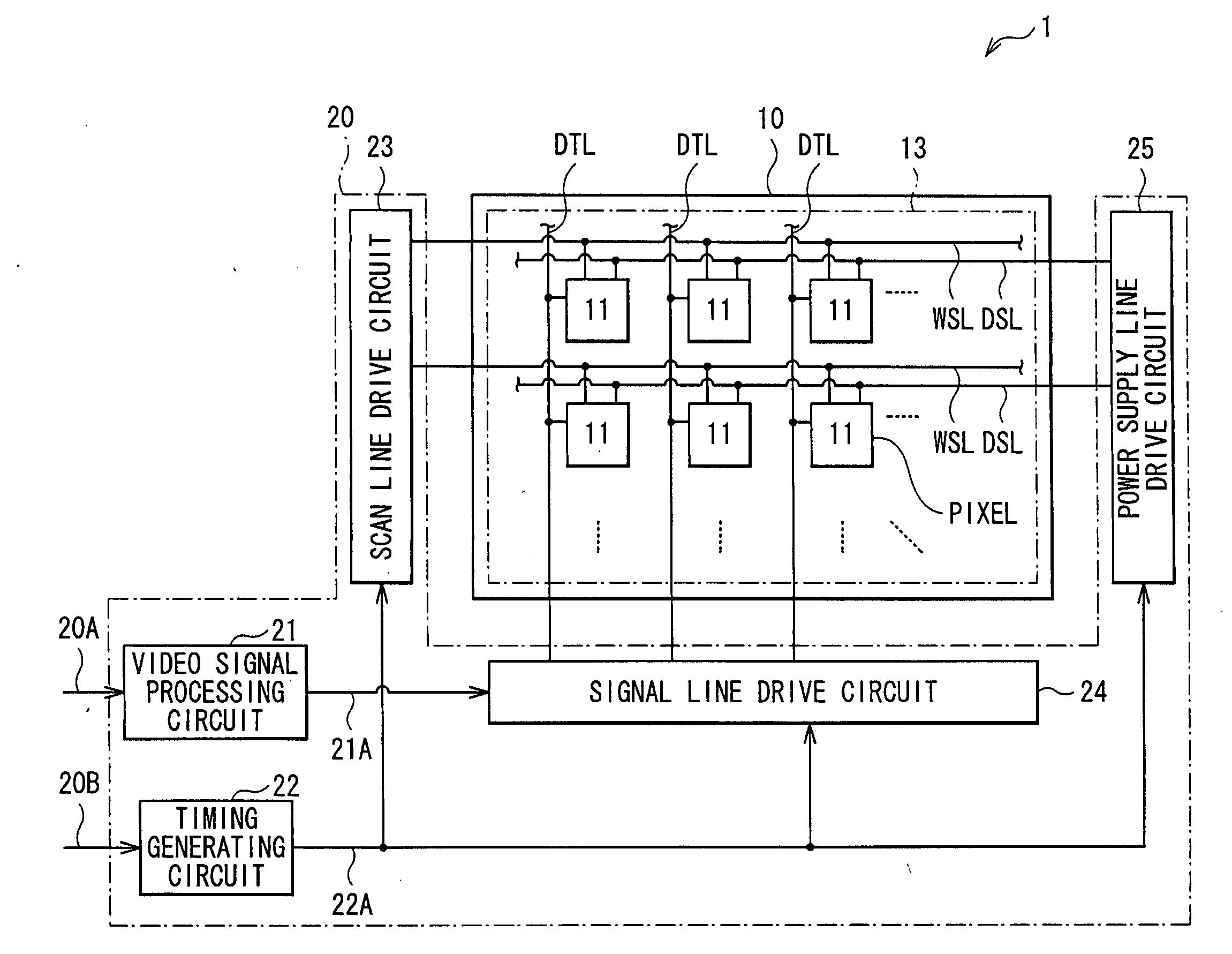
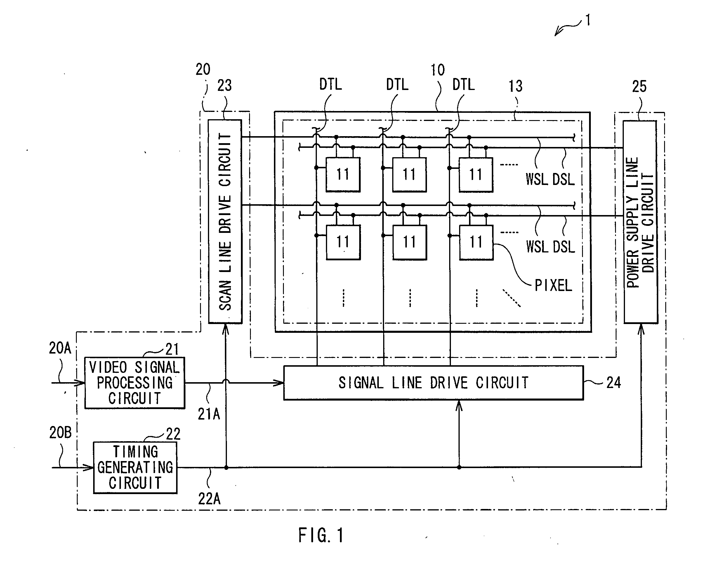
[0058]FIG. 1 is a block diagram illustrating a schematic configuration of a display device (display device 1) according to first to fifth embodiments of the present invention to be described below. The display device 1 has a display panel 10 (display section) and a drive circuit 20.

[0059]Display Panel 10

[0060]The display section 10 has a pixel array 13 in which a plurality of pixels 11 are arranged in a matrix, and displays an image by active matrix driving on the basis of a video signal 20A and a synchronization signal 20B input from the outside. Each pixel 11 is any of pixels of three primary colors of red (R), green (G), and blue (B), and includes an organic electric field light emitting element that generates color light.

[0061]The...


PUM


Abstract

A display device includes: pixels each including a light emitting element; scan lines, signal lines, and power supply lines; a scan line drive circuit applying a selection pulse to the scan lines in succession; a signal line drive circuit applying a signal pulse to the signal lines through switching a gray-scale interpolation voltage, a basic voltage and a video signal voltage, in this order to perform gray-scale interpolation; and a power supply line drive circuit applying a control pulse to the power supply lines. The scan line drive circuit generates the selection pulse through alternately switching an on-voltage and an off-voltage, and applies the pulse to the scan lines so that application of the on-voltage to the scan line starts in a time period of the gray-scale interpolation voltage and the on-voltage is switched to the off-voltage in a time period of the basic voltage.

Description

BACKGROUND OF THE INVENTION[0001]1. Field of the Invention[0002]The present invention relates to a display device using a self light emitting element such as an organic EL (Electro Luminescence) element, a method of driving the same, and an electronic unit having such a display device.[0003]2. Description of the Related Art[0004]In recent years, in the field of a display device for displaying an image, a display device (organic EL display device) using, as a light emitting element, an optical element of a current driving type whose light emission luminance level changes according to the value of a flowing current, for example, an organic EL element, is developed and is being commercialized.[0005]An organic EL element is a self light emitting element different from a liquid crystal element or the like. Consequently, in an organic EL display device, a light source (backlight) is unnecessary. As compared with a liquid crystal display device requiring a light source, visibility of an im...

Claims


Application Information

Patent Timeline
IPC IPC(8): H04N5/70G09G5/00
CPCG09G3/3233G09G2320/045G09G2300/0819
Inventor TOYOMURA, NAOBUMIUCHINO, KATSUHIDE
Owner SONY CORP
Why Eureka
Try Eureka