Power factor correction circuit

a power factor and circuit technology, applied in the direction of power conversion systems, instruments, conversion with intermediate conversion to dc, etc., can solve the problems of increasing the loss of transmission lines, transformers and the like, large amount of cost, and power consumption of plurality of resistors, so as to improve the power factor of input current

Active Publication Date: 2011-05-12
SILICON MITUS
View PDF20 Cites 53 Cited by
  • Summary
  • Abstract
  • Description
  • Claims
  • Application Information

AI Technical Summary

Benefits of technology

[0021]According to the present invention configured as described above, a second coil voltage induced at the secondary coil by input voltage is used, or the input voltage is directly sensed, and then t

Problems solved by technology

Since a switching mode power supply (SMPS) that does not employ a power factor correction circuit generates a pulse-shaped input current, high-order harmonic current flows through transmission lines, and such current does not contribute to power transmission and increases a loss in the transmission lines, transformers and the like.
However, such a prior art needs an additional circuit (including a plurality of resistors or the like) in order to modify th

Method used


Image

  • Power factor correction circuit
  • Power factor correction circuit
  • Power factor correction circuit

Examples


first embodiment

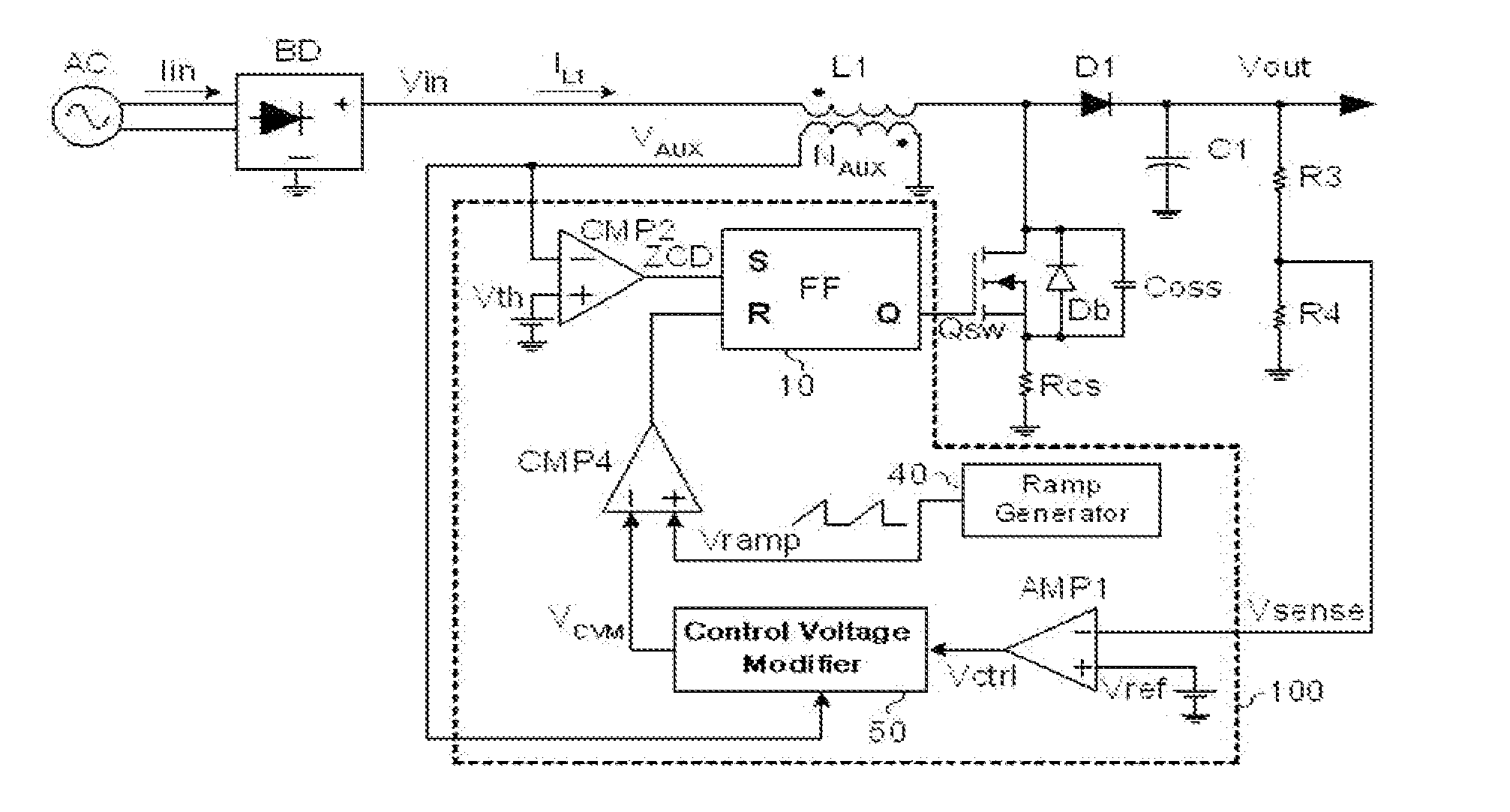
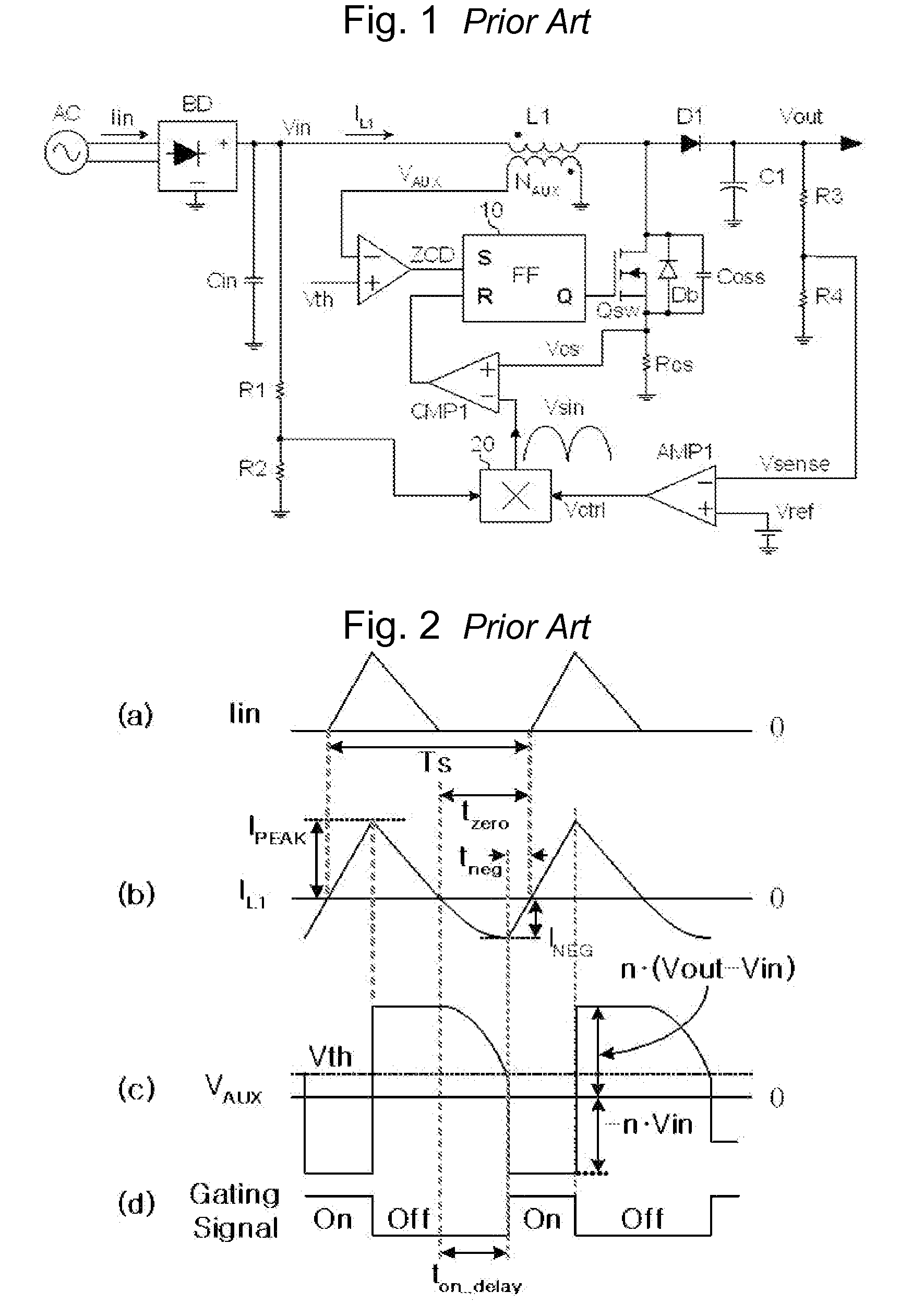
[0050]The bridge diode BD rectifies inputted alternating current AC voltage and outputs a full-wave rectified voltage Vin. The switching control unit 100 receives a sensed output voltage Vsense and a second coil voltage VAUX induced at a second coil NAUX, which is the secondary coil of the inductor L1, and generates a control signal for controlling turn-on / turn-off of the switch Qsw. The switch Qsw is turned on and turned off by the control signal of the switching control unit 100, and a constant direct current voltage Vout is outputted to the capacitor C1 of the boost circuit. Here, the power factor correction circuit according to the present invention differently sets the turn-on period of the switch Qsw depending on the input voltage Vin using the fact that the secondary coil voltage becomes n*Vin when the switch Qsw is turned on as shown in FIG. 2(c), thereby correcting distortion of input current, and the detailed method thereof will be described below. Since the full-wave rect...

third embodiment

[0075]As shown in FIG. 18, the power factor correction circuit according to the present invention receives a second coil voltage VAUX from the waveform generator 60, obtains information on the input voltage Vin, generates a waveform corresponding to the input voltage Vin, and generates a turn-off reference voltage VA0 by adding output voltage VWG0 of the waveform generator 60 to output voltage Vramp of the ramp generator 40 through the adder 210. Since the output voltage VWG0 of the waveform generator 60 increases as the input voltage Vin is increased, output voltage VA0 of the adder 210 meets the first control voltage Vctrl of the output voltage controller AMP1 further earlier as the input voltage Vin increases, and thus switch turn-on time is shortened. Therefore, distortion of input current can be reduced by extending the turn-on time when the input voltage low and reducing the turn-on time when the input voltage high.

[0076]FIG. 19 shows waveforms in the case where output voltage...


PUM


Abstract

The present invention relates to a power factor correction circuit that can reduce distortion of input current in a switching mode power supply. The power factor correction circuit provided in the present invention basically comprises a first inductor which is electrically connected at a first end thereof to an input terminal, a second coil that is coupled to the first inductor to form an induced voltage, a switch electrically connected to the a second terminal of the first inductor, and a switching control unit for controlling turn-on and turn-off of the switch. In such a power factor correction circuit of the present invention, the switching control unit is configured to differently set a turn-on period of the switch depending on the input voltage by generating a signal for controlling the turn-off of the switch using a second coil voltage induced at the secondary coil of the inductor by input voltage or a directly sensed input voltage. Accordingly, distortion of input current can be effectively corrected.

Description

TECHNICAL FIELD[0001]The present invention relates to a power factor correction circuit for use in prevention of power loss invited by reactive power in a switching mode power supply, and more specifically, to a power factor correction circuit, that can correct a distortion of input current in a conventional power factor correction circuit.BACKGROUND ART[0002]Since a switching mode power supply (SMPS) that does not employ a power factor correction circuit generates a pulse-shaped input current, high-order harmonic current flows through transmission lines, and such current does not contribute to power transmission and increases a loss in the transmission lines, transformers and the like. For this reason, the capacity of transmission lines, substations, and power stations is relatively high as compared to a case where a power factor correction circuit is used.[0003]Accordingly, there is a movement in many countries to regulate current harmonic recently, such as EN61000-3-2, and a powe...

Claims


Application Information

Patent Timeline
IPC IPC(8): H02M1/42
CPCG05F1/70
Inventor LEE, JAE HOON
Owner SILICON MITUS
Why Eureka
Try Eureka