Chassis with distributed jet cooling

Inactive Publication Date: 2011-05-19
GENERAL ELECTRIC CO
View PDF27 Cites 34 Cited by
  • Summary
  • Abstract
  • Description
  • Claims
  • Application Information

AI Technical Summary

Problems solved by technology

Cost, size, reliability, and availability have been major constraints.
Natural convection air-cooling is the method of choice for many low power electronics applications due to cost, availability, and reliability.
However, its performance is limited due to buoyancy dependent flow.
Although studies indicate that heat transfer augmentation is possible using synthetic jets, there is limited data available for the application of synthetic jets to large heat sink surfaces.

Method used


Image

  • Chassis with distributed jet cooling
  • Chassis with distributed jet cooling
  • Chassis with distributed jet cooling

Examples


Embodiment Construction

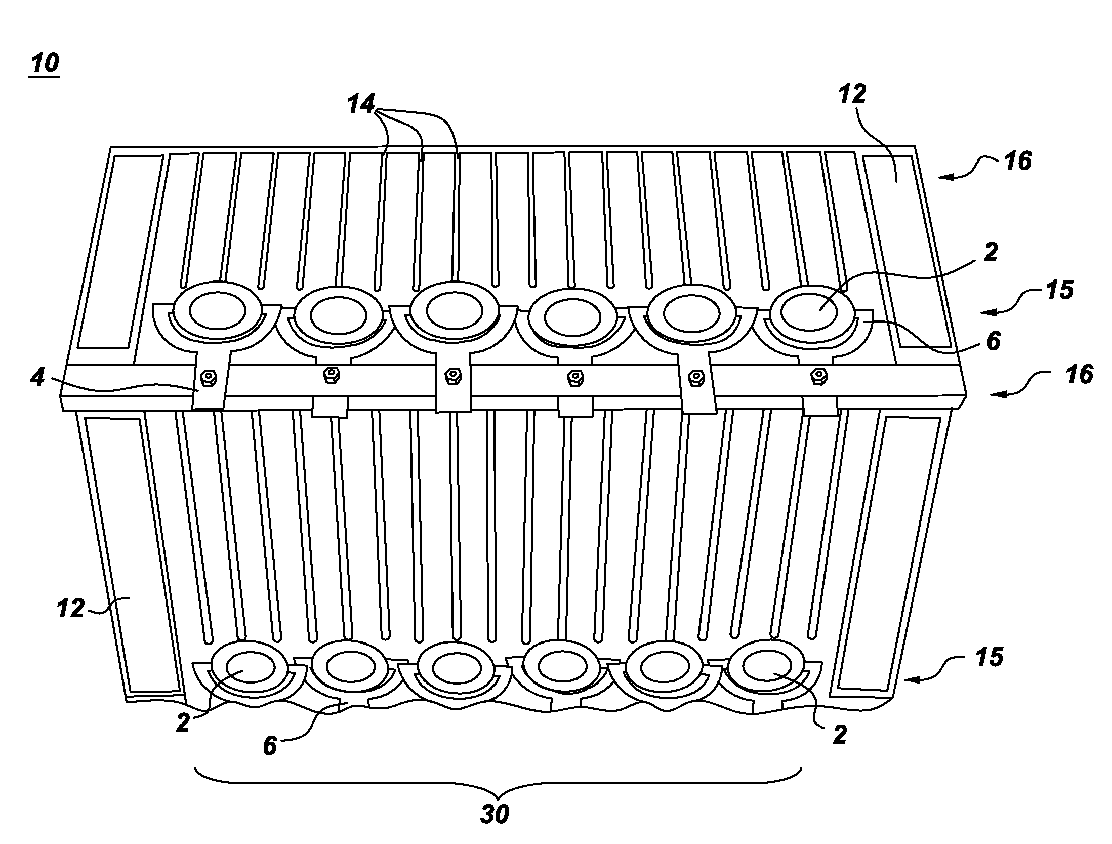
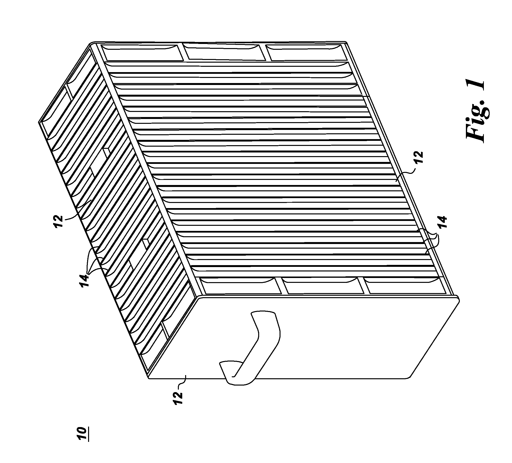
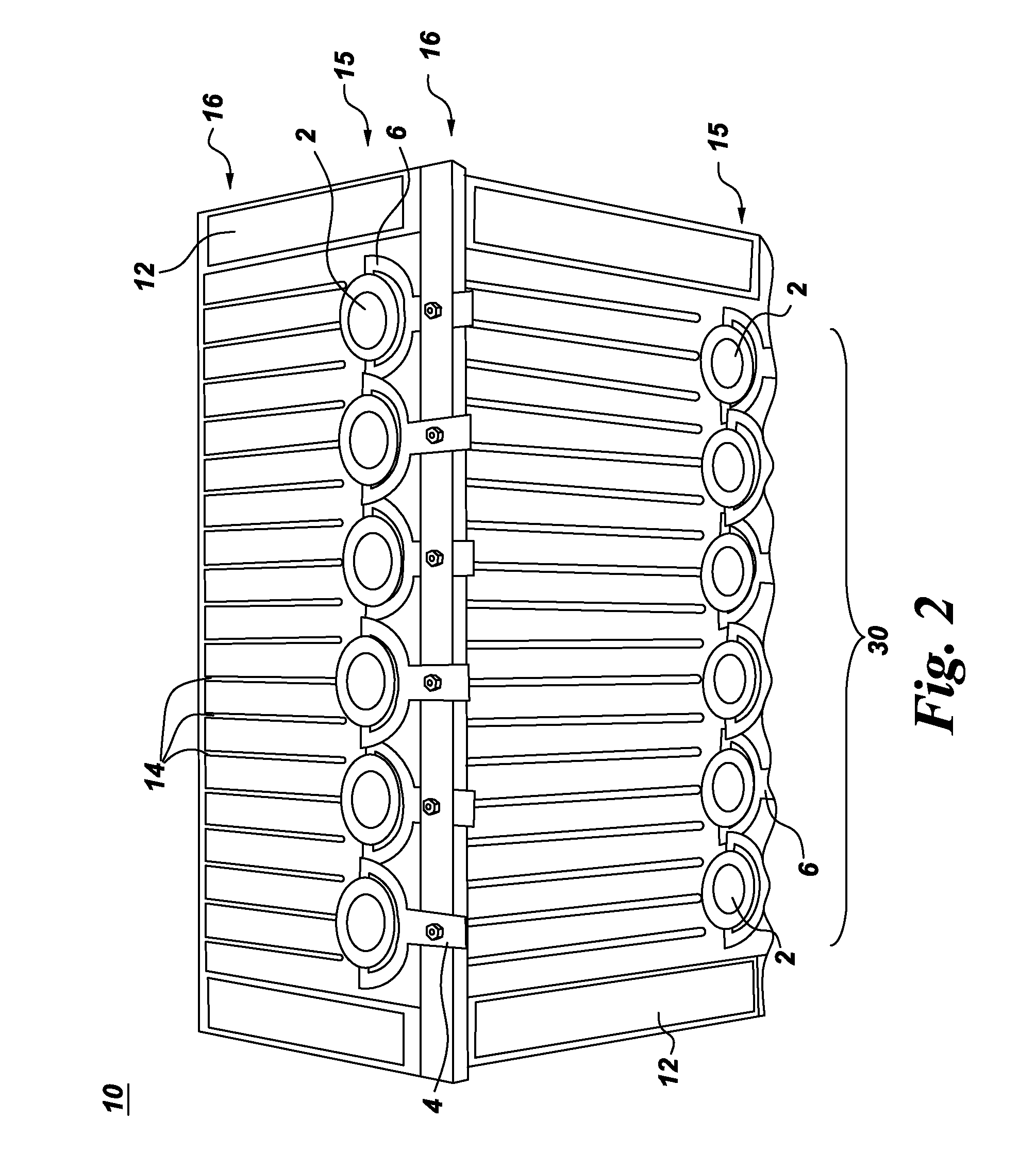
[0030]A chassis 10 with distributed jet cooling is described with reference to FIGS. 1-17. As shown for example in FIG. 1, the chassis 10 includes one or more sidewalls 12 defining a volume (not shown) configured to substantially surround one or more heat generating components (not shown) positioned within the volume. The heat generating components may be any component requiring cooling, non-limiting examples of which include high power processors and power electronics. The chassis further includes at least one array of fins 14 thermally coupled to a respective one of the one or more sidewalls 12. For the arrangement shown in FIG. 1, the fins 14 are longitudinal plate fins. However, other types of fins may be employed, including without limitation, pin fins. Briefly, the heat from the heat generating components is transferred into the sidewalls, which in turn transfer heat into the fins 14. The fins 14 increase the surface area for heat transfer for cooling the heat generating compo...


PUM


Abstract

A chassis with distributed jet cooling is provided. The chassis includes one or more sidewalls defining a volume configured to substantially surround one or more heat generating components positioned within the volume. The chassis further includes at least one array of fins thermally coupled to a respective one of the one or more sidewalls and at least one synthetic jet assembly comprising a multi-orifice synthetic jet or a number of single orifice synthetic jets disposed on a side of a respective one of the array(s) of fins. The chassis further includes at least one attachment means for attaching a respective one of the at least one synthetic jet assemblies to a respective one of the one or more sidewalls.

Description

CROSS REFERENCE TO RELATED APPLICATIONS[0001]This application claims the benefit of U.S. Provisional Patent Application Ser. No. 61 / 262,722, filed Nov. 19, 2009 and entitled “Enhancement of natural convection using synthetic jets,” which is incorporated herein by reference in its entirety.BACKGROUND[0002]The invention relates generally to thermal management systems, and more particularly, to thermal management systems with distributed jet cooling to augment convection heat transfer.[0003]Recent advancements in electronics technology have produced nanometer sized electronic circuits. The resulting advanced electronics, although smaller, have higher heat fluxes. Because thermal real estate has been shrinking, advanced cooling techniques are needed. Cost, size, reliability, and availability have been major constraints.[0004]Natural convection air-cooling is the method of choice for many low power electronics applications due to cost, availability, and reliability. However, its performa...

Claims


Application Information

Patent Timeline
IPC IPC(8): F28F9/00
CPCH05K7/20172H05K7/20209H01L2924/0002H05K7/20009F24F13/02H01L2924/00
Inventor ARIK, MEHMETGERSTLER, WILLIAM DWIGHTLI, RINICEWARNER, EARL ROSSSCHROEDER, CHRISTINA CLYDEVANDER PLOEG, BENJAMIN JONWHALEN, BRYAN PATRICK
Owner GENERAL ELECTRIC CO
Why Eureka
Try Eureka