
Cleaning in membrane filtration systems

a filtration system and membrane technology, applied in the direction of membranes, filtration separation, separation processes, etc., can solve the problems of large amounts of cleaning solution being used unnecessarily, additional cost and environmental impact, and achieve the effect of increasing the amount of chemical cleaning agents present during the clean

Inactive Publication Date: 2011-05-19
EVOQUA WATER TECH LLC
View PDF99 Cites 46 Cited by
  • Summary
  • Abstract
  • Description
  • Claims
  • Application Information

AI Technical Summary

Benefits of technology

The present invention provides a method for cleaning permeable, hollow membranes in a liquid suspension using a chemical cleaning solution. The method involves applying a pressure differential across the membrane walls to induce and sustain filtration through the membrane walls. The cleaning solution is applied to one side of the membrane wall and a reverse pressure differential is applied to cause the cleaning solution to flow through the membrane wall and accumulate in the other side of the membrane. The cleaning process can be repeated in cycles to ensure complete cleaning of the membrane. The invention also provides a method for cleaning membranes in a pressurized membrane filtration system.

Problems solved by technology

This often results in a one process fits all approach where a standard chemical cleaning stage is applied regardless of the amount of fouling.
This can lead to large amounts of cleaning solution being used unnecessarily with the effect of additional cost and environmental impact in disposing of the waste solution after cleaning is complete.

Method used


Image

  • Cleaning in membrane filtration systems
  • Cleaning in membrane filtration systems
  • Cleaning in membrane filtration systems

Examples


Embodiment Construction

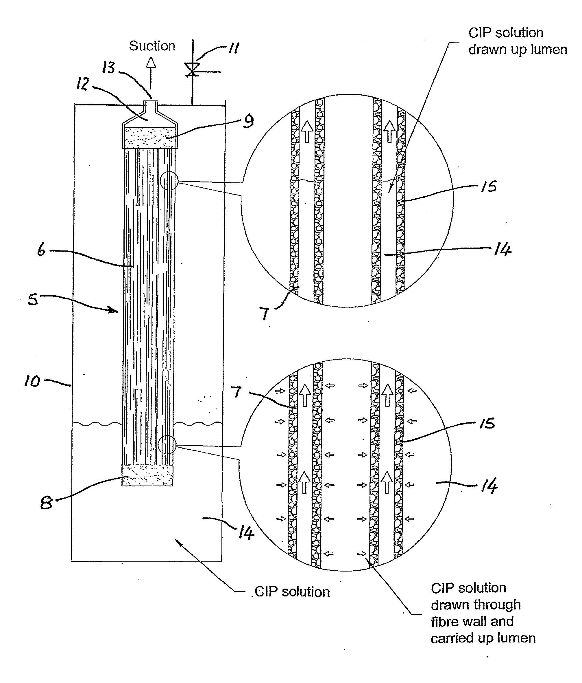
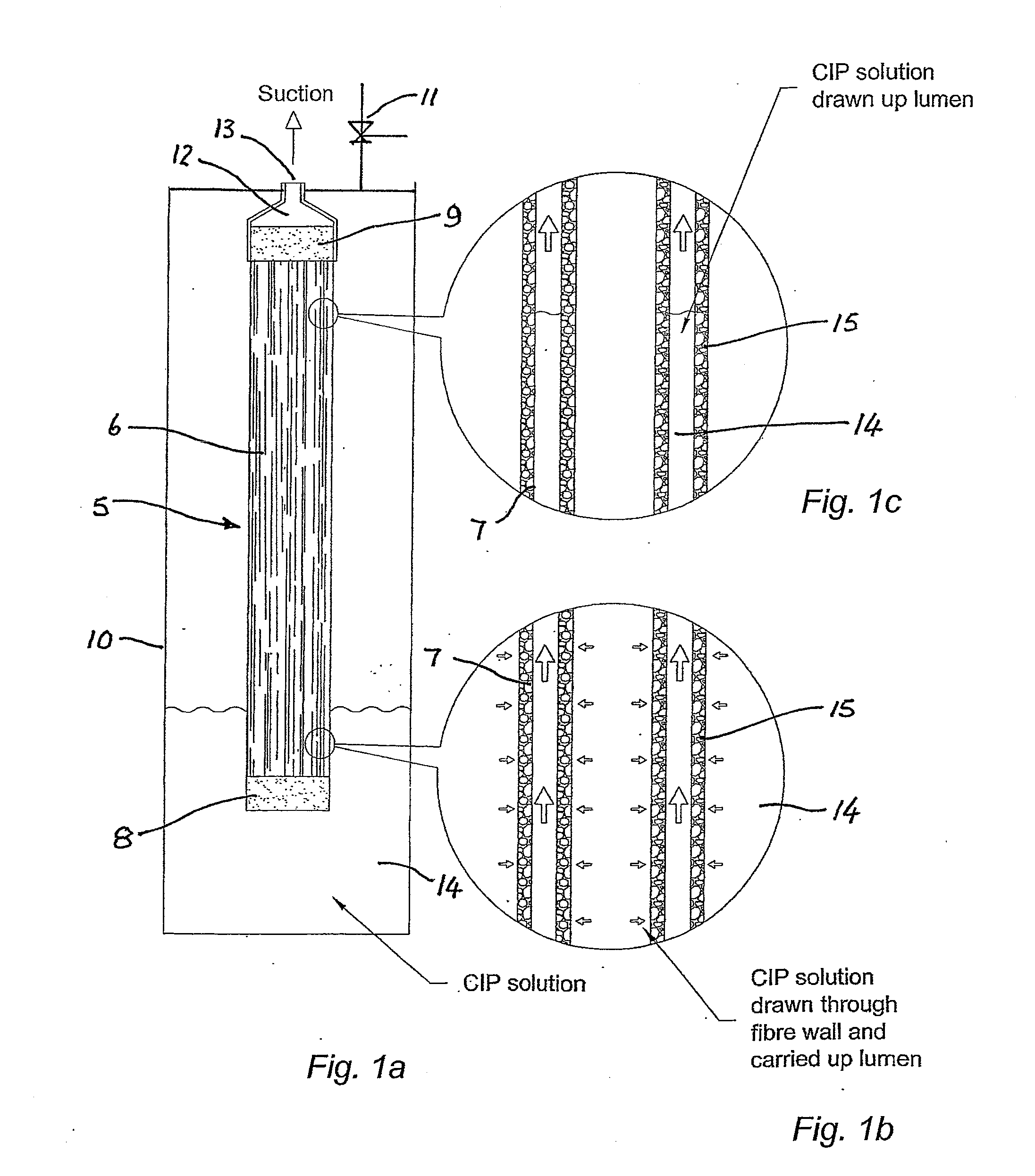
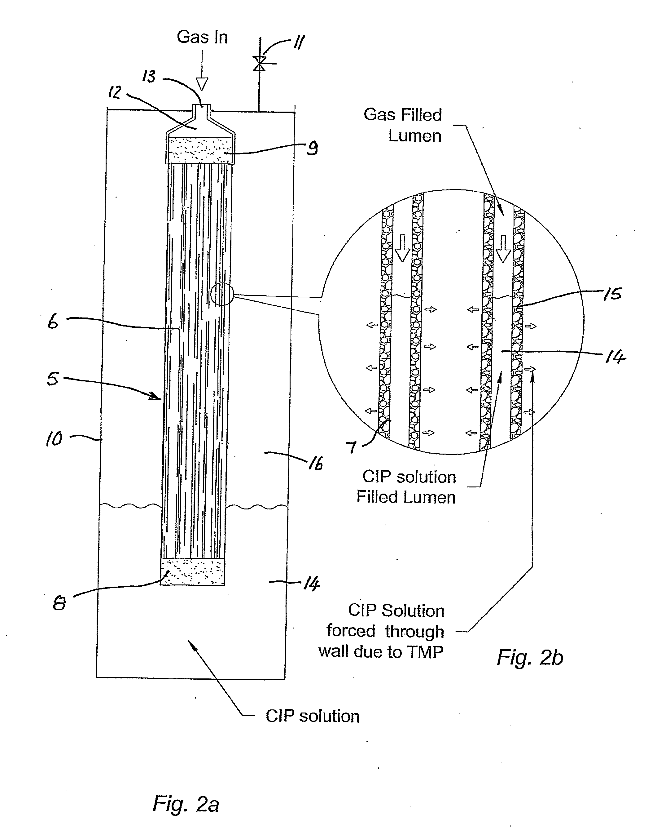
[0084] Referring to the FIGS. 1 to 7, there is shown a membrane module 5 having a plurality of hollow fibre membranes 6. The fibre membranes 6 have their lumens 7 closed at the lower end in a lower pot 8 and open at the upper end through upper pot 9. The module 5 is contained in a vessel 10 having a controllable valve 11 for opening / closing the vessel 10 to atmosphere. Upper pot 8 is connected to a filtrate collection chamber 12 having a port 13.

[0085] One embodiment of the cleaning process according to the invention will now be described with reference to FIGS. 1 to 3. As best shown in FIGS. 1a to 1c, liquid remaining in lumens 7 after filtration is drained while liquid remaining in the vessel 10 is also at least partially drained. The vessel 10 is then, at least partially, filled with cleaning solution 14 as best shown in FIG. 1a. A differential pressure is then applied across the membrane walls 15, in this embodiment by applying a vacuum to port 13, so that the cleaning solution...


PUM

PropertyMeasurementUnit
volumeaaaaaaaaaa
contact timeaaaaaaaaaa
volumeaaaaaaaaaa

Abstract

A method of cleaning permeable, hollow membranes (6) in an arrangement of the type wherein a pressure differential is applied across the walls (15) of the permeable, hollow membranes (6) immersed in a liquid suspension, the liquid suspension being applied to the outer surface of the porous hollow membranes (6) to induce and sustain filtration through the membrane walls (15) wherein some of the liquid suspension passes through the walls (15) of the membranes (6) to be drawn off as clarified liquid or permeate from the hollow membrane lumens (7), and at least some of the solids are retained on or in the hollow membranes (6) or otherwise as suspended solids within the liquid surrounding the membranes (6). The method of cleaning comprises the steps of applying a cleaning solution (14) to one side of the membrane wall (15); applying a pressure differential across the membrane wall (15) to cause flow of the cleaning solution (14) through the wall (15) from the one side of the membrane wall (15) to the other side of the membrane wall (15) and applying a reverse pressure differential across the membrane wall (15) to cause flow of the cleaning solution (14) through the wall (15) from the other side of the membrane wall (15) back to the one side of the membrane wall (15). A method of determining the amount of chemical cleaning solution required is also disclosed.

Description

FIELD OF THE INVENTION [0001] The present invention relates to the backwashing of hollow permeable membranes used in membrane filtration systems and, in particular, to an improved method of backwashing and cleaning the hollow permeable membranes. BACKGROUND ART [0002] Any discussion of the prior art throughout the specification should in no way be considered as an admission that such prior art is widely known or forms part of common general knowledge in the field. [0003] Known backwash systems include those described in our earlier International Application No. WO93 / 02779 the subject matter of which is incorporated herein by cross-reference. [0004] During cleaning of membranes, cleaning solutions are often flowed through the membranes and their permeable walls to clean foulants from the membranes. Applying the cleaning solution under pressure assists the removal of foulants from the surface. [0005] The typical known cleaning procedure for membranes involves cleaning the membranes in...

Claims


Application Information

Patent Timeline
Patent Type & Authority Applications(United States)
IPC IPC(8): B01D65/02
CPCB01D63/02B01D65/02B01D2315/06C02F1/444B01D2321/162B01D2321/164B01D2321/168B01D2321/16
Inventor JOHNSON, WARRENBECK, THOMASYEO, REBECCA
Owner EVOQUA WATER TECH LLC
Learn More