Brake system for motor vehicles

a technology for brake systems and motor vehicles, applied in brake systems, brake components, transportation and packaging, etc., can solve problems such as unpleasant brake pedal sensation for the vehicle driver

Active Publication Date: 2011-05-19
CONTINENTAL TEVES AG & CO OHG
View PDF29 Cites 77 Cited by
  • Summary
  • Abstract
  • Description
  • Claims
  • Application Information

AI Technical Summary

Benefits of technology

[0007]The electrically controllable pressure supply device can preferably be connected directly to one of the master brake cylinder pressure spaces. A 2 / 2 way valve which is closed when no current is flowing (CC) and which can be activated electromagnetically is particularly preferably inserted into the connection between the pressure supply device and the master brake cylinder pressure space.
[0008]The electrically controllable pressure supply device of the brake system according to aspects of the invention is preferably embodied as a hydraulic cylinder-piston arrangement whose piston can be driven by means of an electric motor.
[0009]According to one preferred embodiment of the brake system according to aspects of the invention, a high pressure accumulator is provided which can be charged by the electrically controllable pressure supply device. A check valve (also referred to as an accumulator charging valve) is advantageously inserted into the hydraulic connection between the high pressure accumulator and the electrically controllable pressure supply device.
[0010]A hydraulic brake pressure modulation unit, which permits brake-circuit-specific or wheel-selective braking processes, is preferably inserted between the master brake cylinder and the wheel brakes.
[0011]The brake pressure modulation unit advantageously has pressure regulating valves for carrying out a braking process according to what is referred to as the multiplex principle.
[0012]According to one development of the brake system according to aspects of the invention, all the 2 / 2 way valves which can be activated electromagnetically, the pressure sensors, the pressure supply device and a rotor position sensor which senses the rotor position of an electric motor which forms a component of the pressure supply device are integrated in a hydraulic valve block.
[0013]The valve block preferably contains the pedal decoupling unit with its housing and the simulator device and can be attached to a splash board of the motor vehicle.
[0014]It is likewise preferred that the sensor device for sensing the driver deceleration request be integrated into the valve block and connected to the electronic open-loop and closed-loop control unit without external cables.

Problems solved by technology

When rapid activation of the pedal occurs in the previously known brake system, there is the problem that the electrically controllable pressure supply device, which is embodied as a motor pump assembly, cannot build up the necessary restraining pressure with the same dynamic so that a temporary movement of the restraining piston away from its stop can take place.
This movement results in a brake pedal sensation which is unpleasant for the vehicle driver.

Method used


Image

  • Brake system for motor vehicles
  • Brake system for motor vehicles
  • Brake system for motor vehicles

Examples


Embodiment Construction

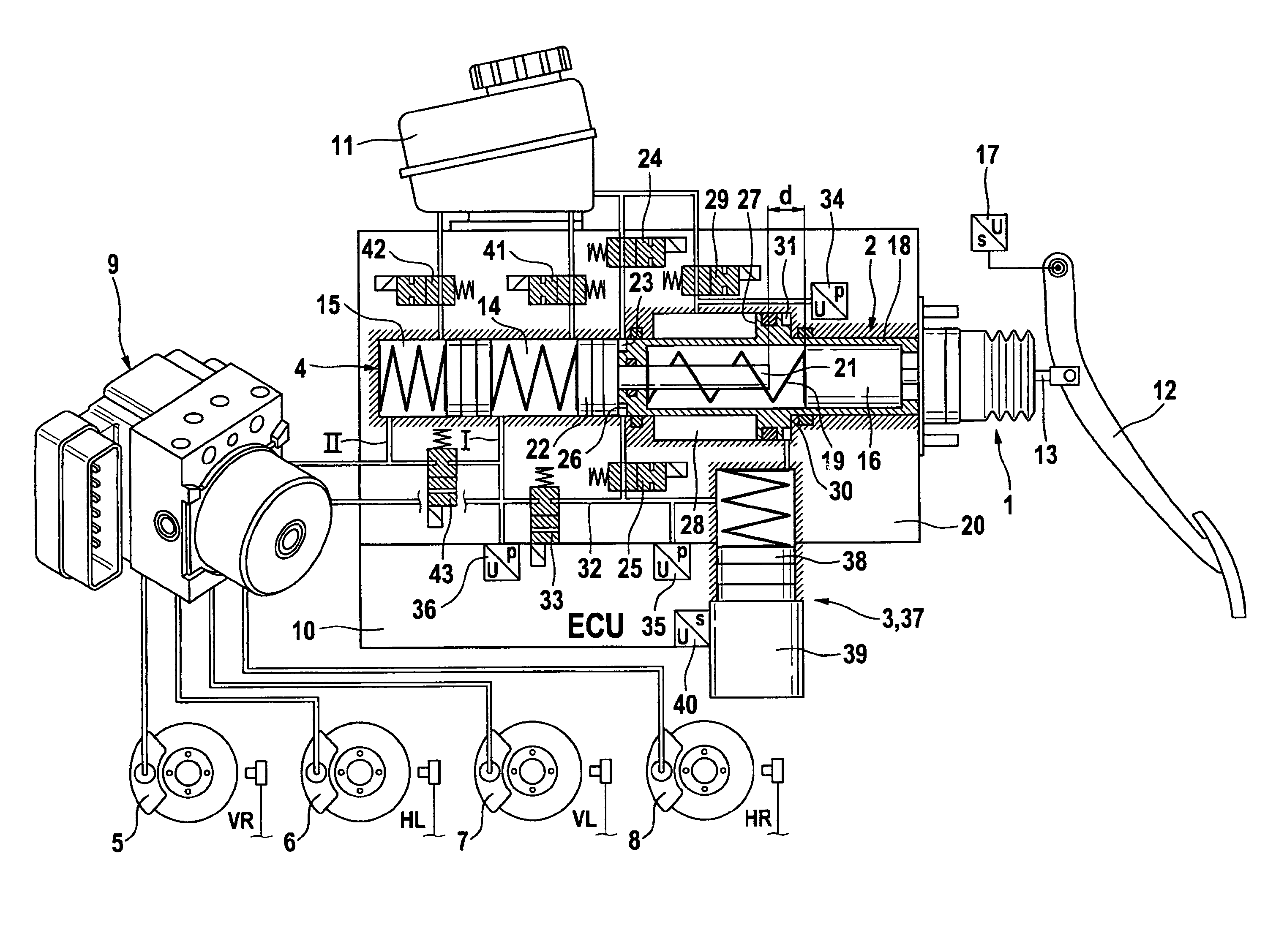
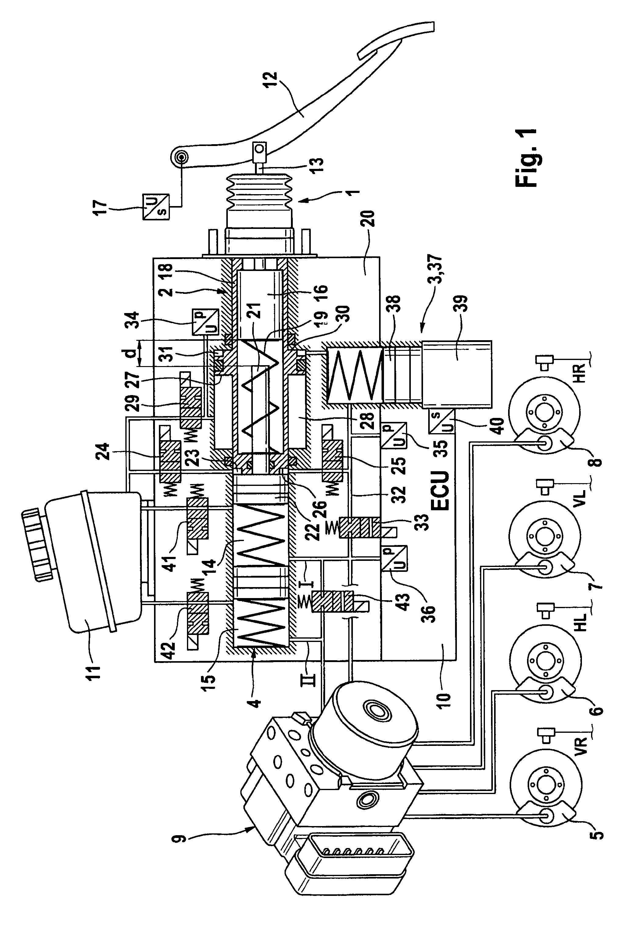
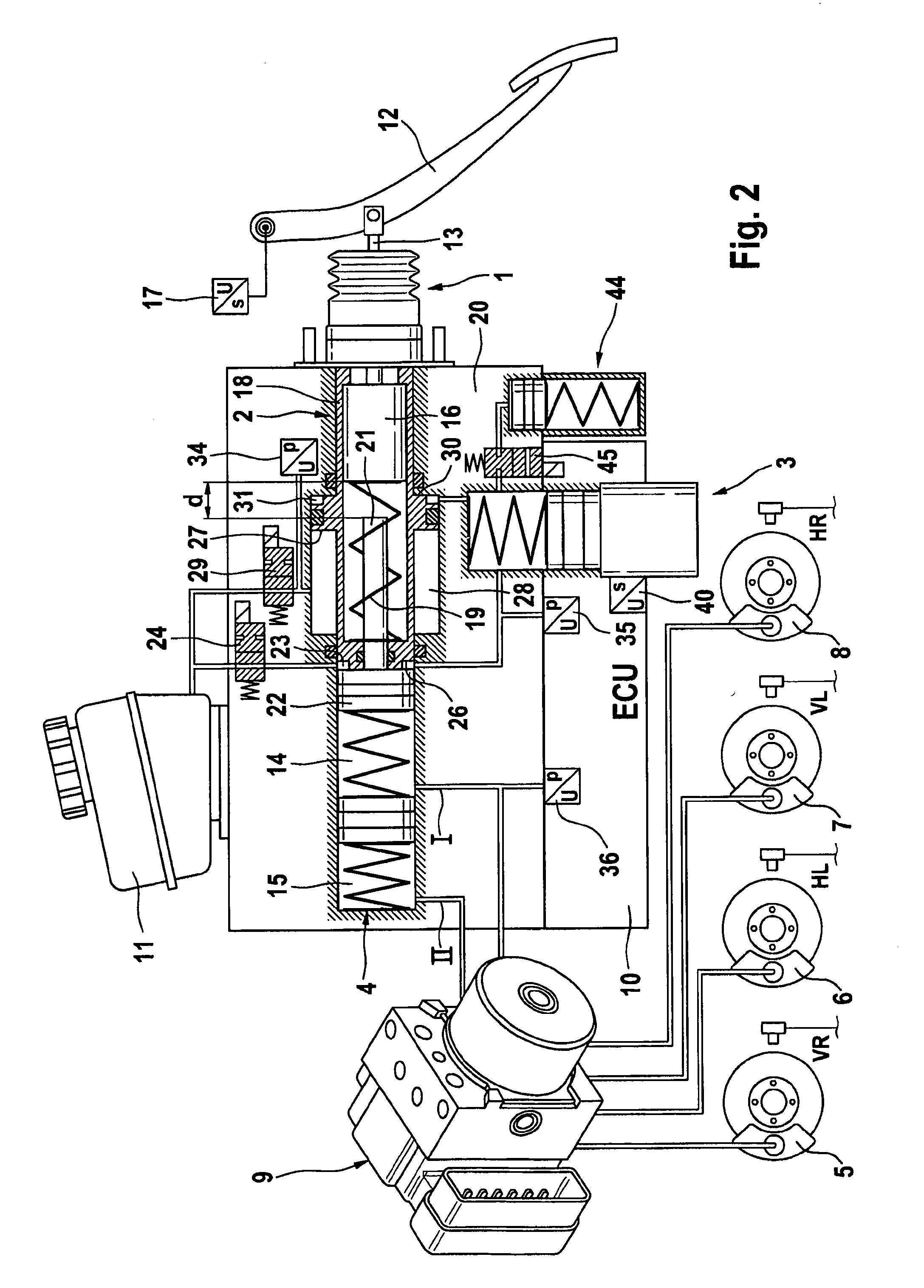
[0020]The brake system according to aspects of the invention which is illustrated in FIG. 1 is composed essentially of an activation device 1, a pedal decoupling unit 2, an electrically controllable pressure supply device 3, wherein the activation device 1 and the pressure supply device 3 form a brake booster, as well a master brake cylinder or tandem master cylinder 4 which is connected downstream of the brake booster in terms of effect and whose pressure spaces 14, 15 can be connected by means of known, so-called expansion holes (not illustrated), to which chambers, under atmospheric pressure, of a pressure medium reservoir vessel 11 can be connected. Furthermore, the aforementioned pressure spaces 14, 15 are connected to the pressure medium reservoir vessel 11 via 2 / 2 way valves 41, 42 which are preferably open when no current is flowing (OC) and can be activated electromagnetically, and their function will be explained later. On the other hand, wheel brake circuits I, II, which ...


PUM


Abstract

A brake system includes a main brake cylinder and a pedal decoupling unit provided with a holding piston, the first ring surface thereof together with a first primary brake cylinder piston defining a first hydraulic chamber that is hydraulically pressurized with an electrically controllable pressure supply device. In order to improve the pedal characteristics of the brake system, in particular in a brake-by-wire brake system, the holding piston is embodied as a differential piston, the second ring surface thereof defining a second, blockable hydraulic chamber, and a piston effect in the second chamber corresponds to a force that acts counter to the direction of actuation on the holding piston.

Description

CROSS REFERENCE TO RELATED APPLICATIONS[0001]This application is the U.S. national phase application of PCT International Application No. PCT / EP2009 / 059124, filed Jul. 16, 2009, which claims priority to German Patent Application No. DE 10 2008 033 785.4, filed Jul. 18, 2008, and German Patent Application No. DE 10 2009 033 499.8, filed Jul. 15, 2009, the contents of such applications being incorporated herein by reference.FIELD OF THE INVENTION[0002]The present invention relates to a brake system for motor vehicles.BACKGROUND OF THE INVENTION[0003]The present invention relates to a brake system for motor vehicles which can be actuated in a brake-by-wire operating mode both by the vehicle driver and independently of the vehicle driver, and is preferably operated in the brake-by-wire operating mode and can be operated in a fallback operating mode without brake boosting, in which fallback operating mode only operation by the vehicle driver is possible. Such a brake system is known from...

Claims


Application Information

Patent Timeline
Patent Type & Authority Applications(United States)
IPC IPC(8): B60T13/00B60T13/66B60T13/74B60T13/12B60T8/40
CPCB60T7/042B60T2201/03B60T13/686B60T8/4077B60T13/143B60T8/40B60T13/12B60T13/66B60T13/74
Inventor DINKEL, DIETERFEIGEL, HANS-JORG
Owner CONTINENTAL TEVES AG & CO OHG
Why Eureka
Try Eureka