Converting device with multiple input terminals and two output terminals and photovoltaic system employing the same

a technology of photovoltaic system and conversion device, which is applied in the direction of dc-ac conversion without reversal, dc network circuit arrangement, semiconductor devices, etc., can solve the problems of high cost, complex fabrication, and the current generated by the two photovoltaic devices must be matched, so as to reduce complexity and wiring and manufacturing costs, and achieve high power efficiency.

Inactive Publication Date: 2011-05-19
DU PONT APOLLO
View PDF5 Cites 40 Cited by
  • Summary
  • Abstract
  • Description
  • Claims
  • Application Information

AI Technical Summary

Benefits of technology

In view of above, a converting device with multiple input terminals and two output terminals is provided which can be coupled to a three-terminal, four-terminal or multiple-terminal photovoltaic module for the higher power efficiency brought by the photovoltaic module, while having reduced complexity and wiring and manufacturing costs. Additionally, a photovoltaic system employing such a converter is also provided.

Problems solved by technology

However, this method not only leads to complex fabrication and hence high costs but also causes difficulty that the currents generated by the two photovoltaic devices have to be matched under all operation conditions for a two-terminal MJs photovoltaic module.
Consequently, the photovoltaic system complexity and manufacturing costs both increase due to extra wirings for the one or two extra terminal.

Method used


Image

  • Converting device with multiple input terminals and two output terminals and photovoltaic system employing the same
  • Converting device with multiple input terminals and two output terminals and photovoltaic system employing the same
  • Converting device with multiple input terminals and two output terminals and photovoltaic system employing the same

Examples


first embodiment

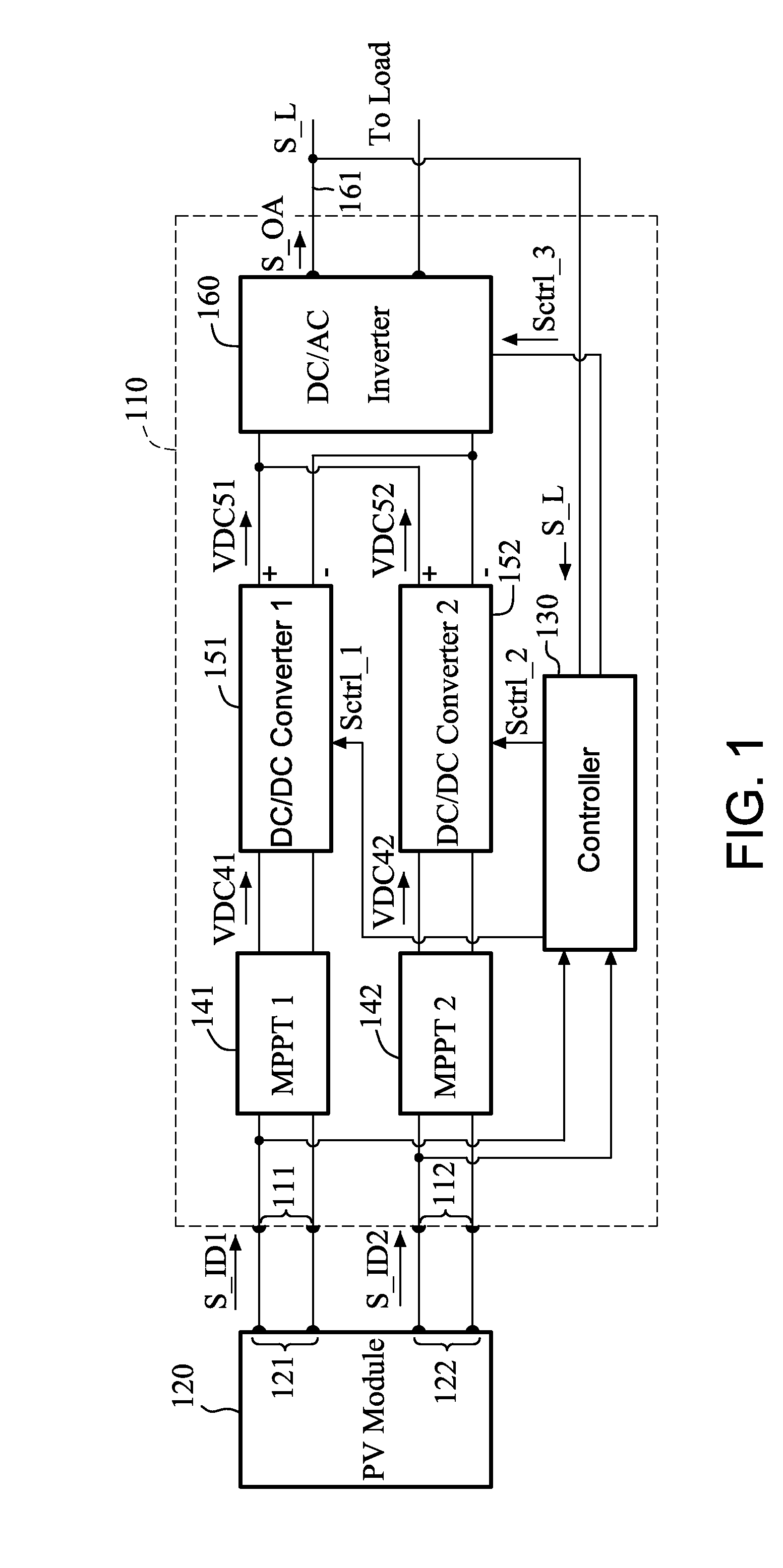
FIG. 1 is a schematic diagram illustrating the architecture of a converter in accordance with a first embodiment;

second embodiment

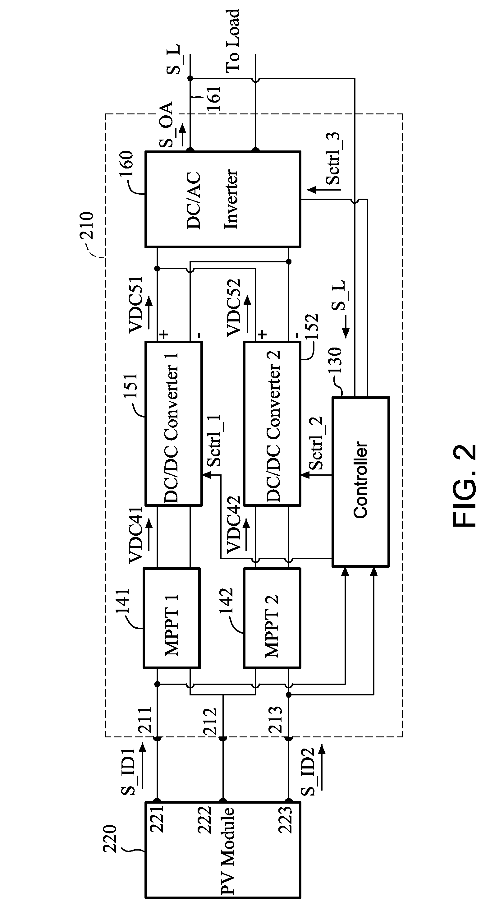
FIG. 2 is a schematic diagram illustrating the architecture of a converter in accordance with a second embodiment; and

third embodiment

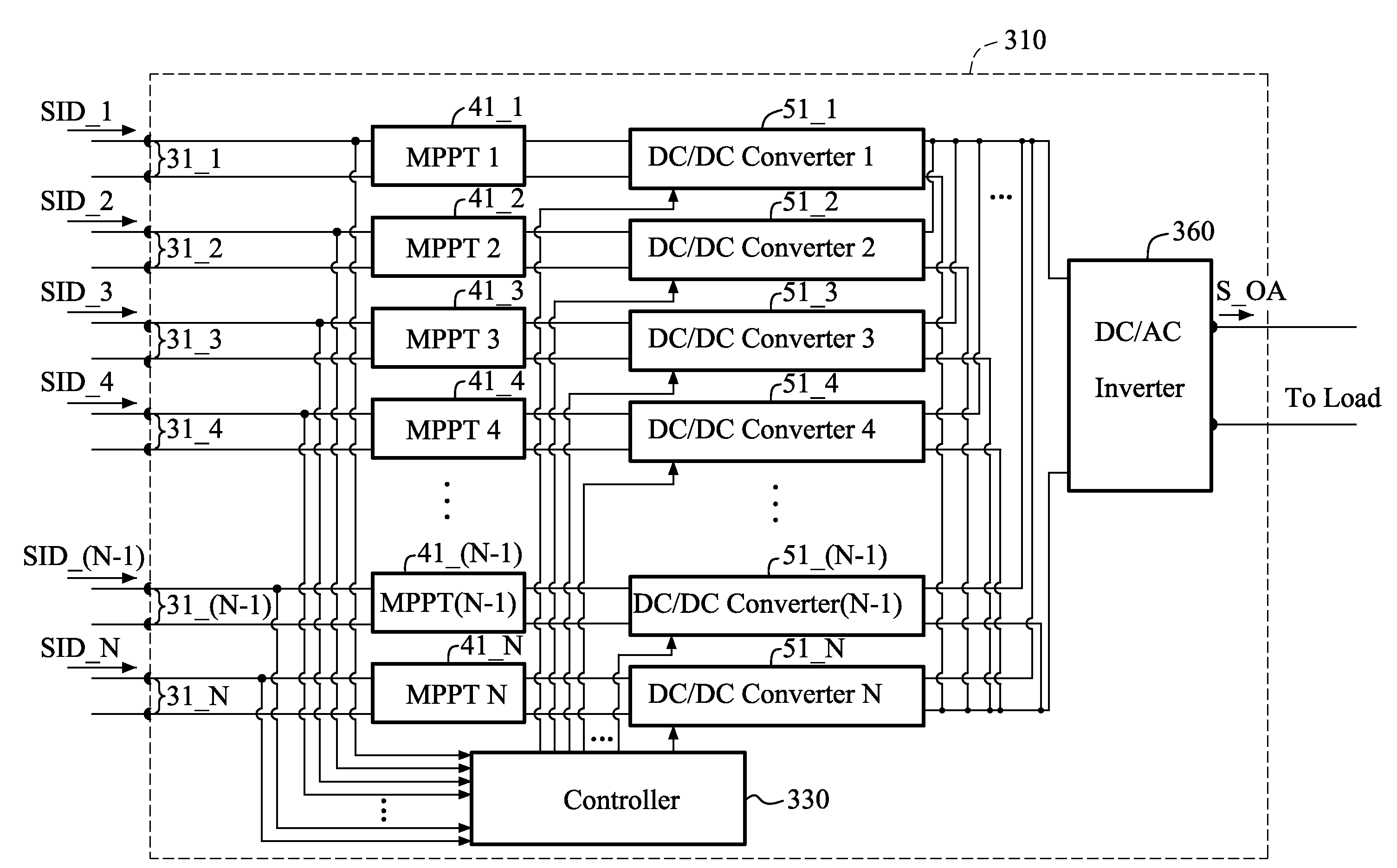
FIG. 3 is a schematic diagram illustrating the architecture of a converter in accordance with a

DETAILED DESCRIPTION OF THE INVENTION

FIG. 1 is a schematic diagram illustrating the architecture of a converter 110 in accordance with a first embodiment, which can convert DC (Direct Current) power from a power source (in the exemplary embodiment, a four-terminal photovoltaic module (PV module) 120) into AC (Alternating Current) power that can be fed to a load such as a power grid (not shown).

As shown, the PV module 120 has four output terminals grouped as two pairs of output electrodes 121 and 122. Correspondingly, the converter 110 includes four input terminals grouped as two pairs of input electrodes 111 and 112, which can be coupled to the pairs of output electrodes 121 and 122, respectively. The converter 110 can receive two DC input signals S_ID1 and S_ID2 respectively at the two pairs of input electrodes 111 and 112 from the PV module 120, and then converts the received DC input si...


PUM


Abstract

A converting device with multiple input terminals and two output terminals is disclosed for converting Direct Current (DC) power from a power source to Alternating Current (AC) power. The converting device includes N pairs of input electrodes (N is an integer and N≧2), configured to receive the DC power from the power source, N maximum power point trackers, each coupled to one pair of the N pairs of input electrodes, configured to track a maximum power operation point for the DC power received from the one pair of the N pairs of input electrodes, two DC/DC converters, each coupled to one of the N maximum power point trackers, configured to convert a DC voltage received from the one of the N maximum power point trackers, a DC/AC inverter, coupled to the N DC/DC converters, configured to convert N DC voltages provided by the N DC/DC converters to an AC output signal, and a controller, coupled to the N DC/DC converters and the DC/AC inverter, configured to control the DC/DC conversion operation of the N DC/DC converters and the DC/AC conversion operation of the DC/AC inverter.

Description

Field of the InventionThe invention relates generally to a converting device and photovoltaic system and, more particularly, to a converting device with multiple input terminals and two output terminals that can convert DC power from a three-terminal, four-terminal or multiple-terminal photovoltaic module to AC power, and a photovoltaic system employing the same.BACKGROUND OF THE INVENTIONEnvironmental concerns and the search for alternative sources of energy relative to fossil fuel energy sources have driven the need for photovoltaic systems, which can process sunlight into electric power for supplying households or small commercial sites.Conventional photovoltaic power systems typically include a plurality of interconnected photovoltaic modules, which are often referred to as an array, and one or more inverters coupled to the photovoltaic modules to convert DC power from the photovoltaic modules to AC power. As production of solar energy becomes competitive in costs and efficiency...

Claims


Application Information

Patent Timeline
Patent Type & Authority Applications(United States)
IPC IPC(8): H02M7/42
CPCH01L31/02021H02J1/102Y02E10/58Y02E10/563H02J3/383H02J2300/24H02J3/381Y02E10/56H02J2300/26
Inventor CHIANG, HUO-HSIENWANG, CHIOU FU
Owner DU PONT APOLLO
Why Eureka
Try Eureka