Tilted Printed Circuit Board Installation

Active Publication Date: 2011-05-19
AVAGO TECH INT SALES PTE LTD
View PDF9 Cites 0 Cited by
  • Summary
  • Abstract
  • Description
  • Claims
  • Application Information

AI Technical Summary

Benefits of technology

[0016]Accordingly, the present invention provides an improved blade, which includes a single printed circuit board mounted at a tilt angle within a blade pan assembly. The single printed circuit board extends substantially the entire depth of the blade (i.e., from the front end of the blade to the rear end of the blade). In one embodiment, the tilt angle causes the front end of the printed circuit board (i.e., the end of the printed circuit board located adjacent to the front end of the blade) to be positioned slightly higher than the rear end of the printed circuit board (i.e., the end of the printed circuit board located adjacent to the read end of the blade). This configuration provides additional space below the printed circuit board at the front end of the blade. This configuration allows media interface modules mounted in a belly-to-belly configuration at the front end of the printed circuit board to be fitted into the front end of the blade.
[0017]In another embodiment, the tilt angle causes the front end of the printed circuit board to be positioned slightly lower than the rear end of the printed circuit board. This configuration provides additional space above the printed circuit board at the front end of the blade. This configuration allows relatively tall media interface modules mounted on the upper surface of the front end of the printed circuit board to be fitted into the front end of the blade.

Problems solved by technology

Note that positioning PCB 102 at the middle of the slot height HS is not optimal (because such positioning would undesirably, and unnecessarily, increase the required slot height).

Method used


Image

  • Tilted Printed Circuit Board Installation
  • Tilted Printed Circuit Board Installation
  • Tilted Printed Circuit Board Installation

Examples


Embodiment Construction

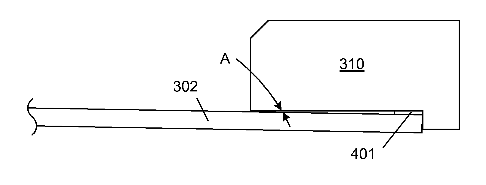
[0030]FIG. 3 is a cross-sectional view of a rack-mountable blade 300 in accordance with one embodiment of the present invention. Blade 300 includes blade pan assembly 301, printed circuit board (PCB) 302, blade hardware 303-304, media interface modules 305-306, PCB mounting structures 307-309, and high-density backplane connector 310. FIG. 3 also illustrates a chassis 120, slot 121, backplane 130 and high-density interconnect socket 131, which are described above in more detail in connection with FIGS. 1A-1B and 2.

[0031]PCB 302 extends from the front edge of blade 300 to the rear edge of blade 300, as illustrated. Blade hardware 303 and 304 is located on the upper and lower surfaces of PCB 302, respectively, as illustrated in FIG. 3. Blade hardware 303 and 304 may include, for example, integrated circuit chips, discrete circuit elements (e.g., resistors and capacitors), heat sinks and / or interconnect structures, which are located on the upper and lower surfaces of PCB 302, respectiv...


PUM

PropertyMeasurementUnit
Angleaaaaaaaaaa
Heightaaaaaaaaaa
Distanceaaaaaaaaaa

Abstract

A blade for a chassis-based system includes a printed circuit board (PCB) mounted at a tilt angle within the blade. The tilt angle provides space above or below the PCB at the front end of the blade, such that media interface modules can be flexibly positioned within the blade. A tilt angle that positions the PCB higher near the front end of the blade may enable media interface modules mounted in a belly-to-belly configuration on the PCB to be fitted within the front end of the blade. A tilt angle that positions the PCB lower near the front end of the blade may enable media interface modules mounted on the upper surface of the PCB to be fitted within the first end of the blade. The tilt angle also positions a backplane connector mounted on the PCB to properly engage a backplane when the blade is inserted into a slot.

Description

FIELD OF THE INVENTION[0001]The present invention relates to a blade used in a chassis-based system. More specifically, the present invention relates to the tilted installation of a printed circuit board within a blade.RELATED ART[0002]FIG. 1A is an isometric view of a conventional rack-mountable blade 100, which includes blade pan assembly 101, printed circuit board (PCB) 102, blade hardware 103-104, media interface module 105, PCB mounting structures 106-108 and high density backplane connector 109. FIG. 1B is a cross-sectional view of blade 100 along section line B-B of FIG. 1A. FIG. 1B also illustrates a portion of a chassis 120 having an associated slot 121 for receiving blade 100, along with a portion of a backplane 130, which is coupled to chassis 120, and a high density backplane connector 131, which is coupled to backplane 130.[0003]Blade pan assembly 101 includes a flat bottom portion 101A, and an upright faceplate portion 101B. Blade pan assembly 101 is typically formed f...

Claims


Application Information

Patent Timeline
IPC IPC(8): H05K5/00H01S4/00
CPCH05K7/142H05K7/1487Y10T29/49002Y10T29/49124H05K13/04
Inventor SKIRMONT, DAVID A.KILKENNY, DANIEL K.
Owner AVAGO TECH INT SALES PTE LTD
Why Eureka
Try Eureka