Electric shock prevention apparatus

Active Publication Date: 2018-11-08
AMOTECH
View PDF0 Cites 1 Cited by
  • Summary
  • Abstract
  • Description
  • Claims
  • Application Information

AI Technical Summary

Benefits of technology

The present invention is an electric shock protection apparatus that can protect the user or internal circuit from leakage currents due to external power sources and efficiently utilize space on the circuit board. The apparatus can pass communication signals and static electricity without a dielectric breakdown. By stacking the electric shock protection apparatus and a contactor for connecting a conductor and circuit board in a portable electronic device, the apparatus can prevent damage to the user or internal circuit due to electric shock. Additionally, the invention minimizes space required for mounting two components on the circuit board.

Problems solved by technology

However, in a case in which the Y-CAP does not have regular features as in a non-genuine charger, the DC power may not be sufficiently blocked by the Y-CAP, furthermore, a leakage current may occur due to the AC power, and the leakage current may flow through the ground of the circuit.
Since the leakage current may be transferred to a conductor contactable with the human body, e.g., an external case of the portable electronic device, a user may experience a prickling discomfort, and in a severe case, an electric shock accident may occur in which the user may suffer injury.
Furthermore, in a case in which the metal housing is used as an antenna, since a signal may be attenuated when the conductive gasket or the conductive contactor has low capacitance, the radio frequency (RF) signal may not be smoothly transmitted.
However, since additional components and elements are required for implementing these various functions and accordingly, an additional space in the circuit board of the portable electronic device must be secured, this may adversely affect the miniaturization of the portable electronic device.

Method used


Image

  • Electric shock prevention apparatus
  • Electric shock prevention apparatus
  • Electric shock prevention apparatus

Examples


Embodiment Construction

[0056]Hereinafter, embodiments of the present disclosure will be described in detail with reference to the accompanying drawings so that those skilled in the art can easily carry out the present disclosure. The present disclosure may be embodied in various ways and is not limited to the embodiments described herein. In the drawings, parts not relating to the description may be omitted for clarifying the present disclosure, and the same reference numerals may be assigned to the same or similar components throughout the specification.

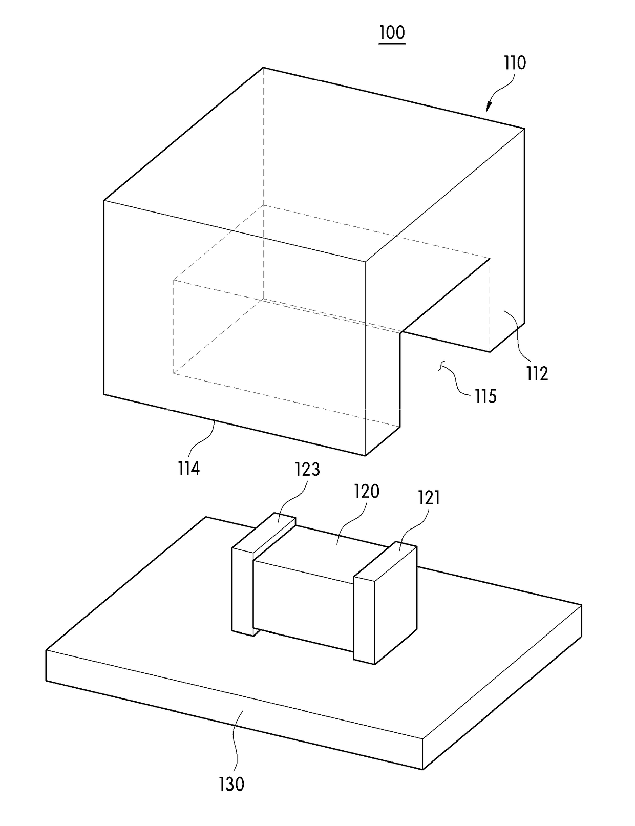
[0057]An electric shock protection apparatus 100 according to an embodiment of the present invention comprises a conductive connection part 110, an electric shock protection device 120, and a circuit board 130.

[0058]Such an electric shock protection apparatus 100 is for electrically connecting a human-contactable conductor such as an external metal case and a circuit board of a portable electronic device, in the portable electronic device.

[0059]Here, the ...


PUM


Abstract

Provided is an electric shock protection apparatus. The electric shock protection apparatus, according to one exemplary embodiment of the present invention, comprises: a conductive connection part comprising an upper surface, which electrically comes into contact with a conductor of an electronic device, comprising an accommodation part containing a predetermined space formed at a lower part thereof, and having elastic force; a circuit board having a conductive connection part mounted therein; and an electric shock protection device mounted on the circuit board such that at least a portion of the electric shock protection device is disposed at the accommodation part, and blocking leakage current of an external power source which flows into a grounding part of the circuit board, wherein the circuit board comprises a pad and a wiring such that the conductive connection part and the electric shock protection device are electrically connected in series.

Description

FIELD OF THE DISCLOSURE[0001]The present invention relates to an electric shock protection apparatus, and more particularly, to an electric shock protection apparatus capable of protecting a user from a leakage current by a power source with an electrical connection between a conductor and a circuit board.DESCRIPTION OF RELATED ART[0002]In line with miniaturization and multifunctional operation of recent portable electronic devices, various components and elements are densely arranged in the portable electronic devices. Thus, in order to reduce impact from the outside as well as electromagnetic waves penetrating into the portable electronic device or leaked from the portable electronic device, a conductive gasket is used between an external housing and a built-in circuit board of the portable electronic device.[0003]Also, due to the multifunctional operation, the portable electronic device may include a plurality of antennas for each function, and at least a portion thereof, as a bu...

Claims


Application Information

Patent Timeline
IPC IPC(8): H05K9/00H01C7/12G06F1/16
CPCH05K9/0009H01C7/12G06F1/1656H01T4/12H01C1/01H01C7/1006H01C7/123H01C7/126H01G2/06H04M1/0202H01T4/02
Inventor RYU, JAE SUCHOI, YUN SUKHWANG, YOON-HOLIM, BYUNG GUK
Owner AMOTECH
Why Eureka
Try Eureka