
Interface system for editing video data

a video data and interface technology, applied in the field of user interface of video data editing software, can solve the problem of difficult to grasp content of individual dynamic image data files, and achieve the effect of efficient editing of video data and easy checking and selecting individual

Inactive Publication Date: 2011-05-19
LOILO
View PDF4 Cites 59 Cited by
  • Summary
  • Abstract
  • Description
  • Claims
  • Application Information

AI Technical Summary

Benefits of technology

[0018]According to the present invention, it is possible to edit video data efficiently by making it easy to check and select individual dynamic image data items in editing the video data.

Problems solved by technology

In this case, there is a problem that the contents of the individual dynamic image data files are hard to grasp by an application such as Explorer (registered trademark) for presenting a list of file names only.
In this respect, it is also possible to generate thumbnail images from the individual dynamic image data files and display the thumbnail images on the screen as icons in a selectable state, but the thumbnail images are also still images per se, which does not meet a user's (operator's) purpose for selecting a dynamic image data file while imagining how the file appears to him / her in a playback state.

Method used


Image

  • Interface system for editing video data
  • Interface system for editing video data
  • Interface system for editing video data

Examples


first embodiment

[0080]An embodiment of the present invention is described with reference to the drawings.

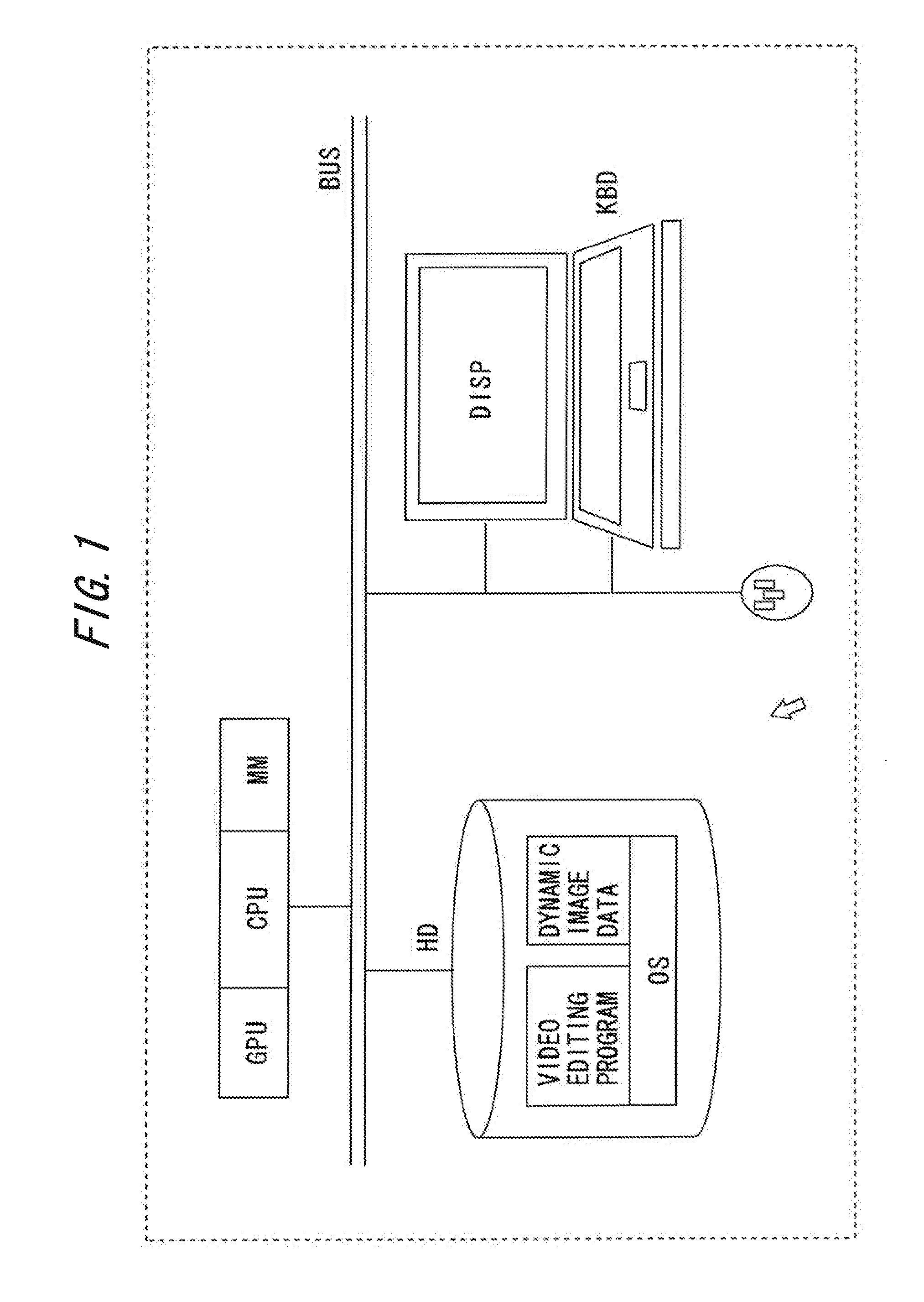
[0081]FIG. 1 is a block diagram illustrating a hardware configuration according to this embodiment.

[0082]In this embodiment, a user interface is employed as a part of a video data editing program, and the program is installed within a hard disk drive (HD) of a personal computer.

[0083]The personal computer includes, as its main components, a central processing unit (CPU), a graphics processing unit (GPU), and a main memory (MM), and also includes the hard disk drive (HD) serving as a large-scale storage device connected thereto by a bus (BUS), a keyboard (KBD) serving as an input device, a mouse (MOU) serving as an auxiliary input device, and a display device (DISP) serving as an output device.

[0084]Within the hard disk drive (HD), a video editing program is installed along with an operating system (OS), and functions of the video editing program are realized by the video editing program being se...

second embodiment

[0127]In this second embodiment, for the video editing program according to the present invention, a characteristic user interface obtained by further improving the first embodiment is described with reference to the drawings.

[0128](Timeline Window and Timeline Bar)

[0129]In this embodiment, the user interface illustrated in FIG. 52 is provided. This interface includes a timeline bar provided with a time scale in the middle, a timeline thumbnail window (details of which are displayed in FIG. 53) located in an upper portion thereof, and a timeline window (editing region) in a lower portion thereof. Further arranged on the timeline bar are operation buttons and the like for controlling the playback of the dynamic image, which include a resolution specifying menu box, a volume adjusting bar, an in point button, a slow rewind / frame-by-frame reverse button, a playback / pause button, a slow fast-forward / frame-by-frame advance button, and an out point button.

[0130]Further, a playback range d...


PUM


Abstract

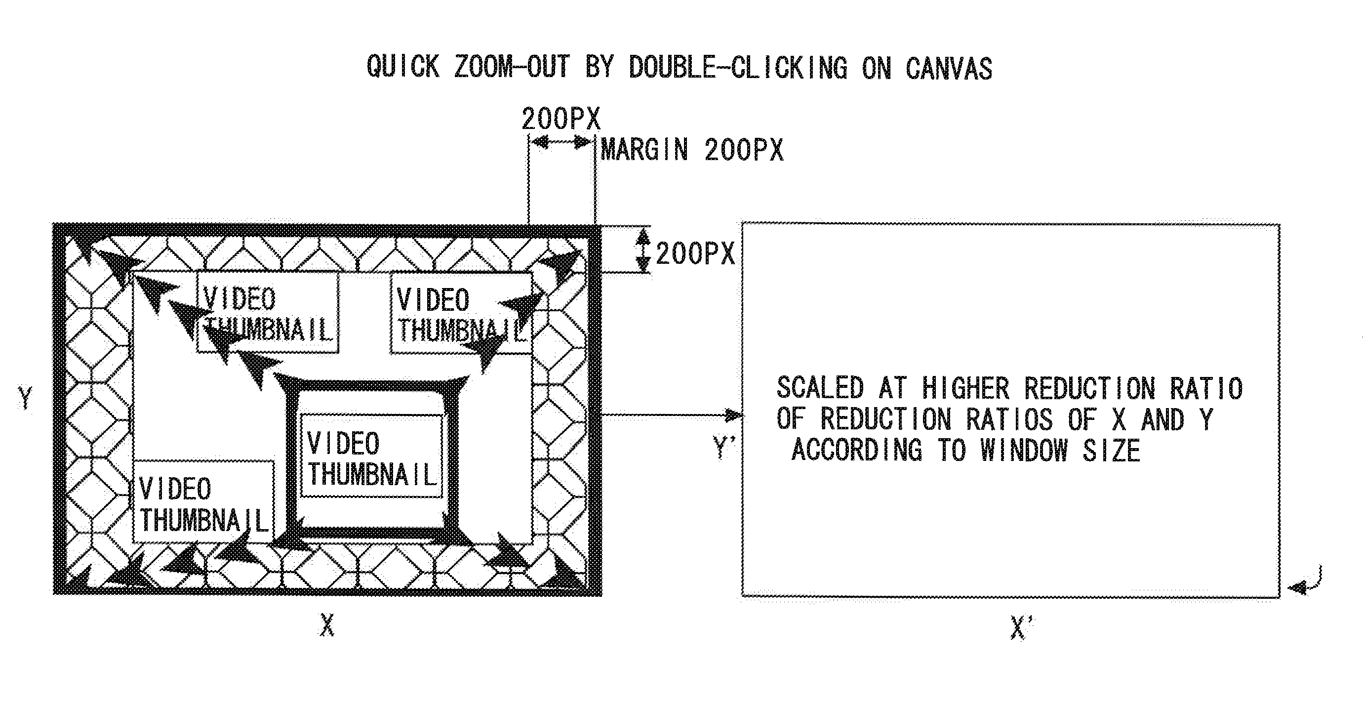
Provided is a user interface system which can facilitate dynamic data check and selection upon video data edition and can effectively perform video data edition. It is possible to execute a dynamic image reproduction in a thumbnail icon region by mouseovering thumbnail icons displayed on a display and symbolizing the dynamic image data. By performing double / single click, it is possible to perform zoom in and zoom out. Thus, it is possible to perform various displays when discarding and selecting dynamic image data, thereby facilitating the video data edition.

Description

TECHNICAL FIELD [0001]The present invention relates to a user interface of video data editing software used for editing video data such as a dynamic image and an image.BACKGROUND ART [0002]In general, dynamic image editing software used on a personal computer performs tasks of reading dynamic image data files stored on a medium such as a hard disk, deleting an unnecessary portion, adding an image effect such as an effect, deciding a playback order of dynamic image data items on a timeline, and publishing a new dynamic image file therefrom.[0003]That is, a task of editing video data involves handling a large number of dynamic image data files, which requires a task of selecting those dynamic image data items on a screen.[0004]In this case, there is a problem that the contents of the individual dynamic image data files are hard to grasp by an application such as Explorer (registered trademark) for presenting a list of file names only.[0005]In this respect, it is also possible to gener...

Claims


Application Information

Patent Timeline
IPC IPC(8): H04N5/93
CPCG06F3/0481G06F3/04817G06F3/0482G06F3/0486G11B2020/10537G11B27/034G11B27/326G11B27/34G06F2203/04806
Inventor SUGIYAMA, KOJISUGIYAMA, RYUTARO
Owner LOILO
Learn More