Wave energy converter

a converter and wave energy technology, applied in the field ofwave energy converters, can solve the problems of difficult economic utilization of this energy

Inactive Publication Date: 2011-05-19
JOSPA
View PDF1 Cites 14 Cited by
  • Summary
  • Abstract
  • Description
  • Claims
  • Application Information

AI Technical Summary

Benefits of technology

[0035]In one embodiment, the mouth comprises a plate located to cut the top of a wave to take advantage of the momentum of the forward-rotating portion of the water in the top of the wave.

Problems solved by technology

The oceans contain vast amounts of concentrated energy in the form of waves but harnessing this energy economically is very difficult.

Method used


Image

  • Wave energy converter
  • Wave energy converter
  • Wave energy converter

Examples


first embodiment

, FIGS. 1-3

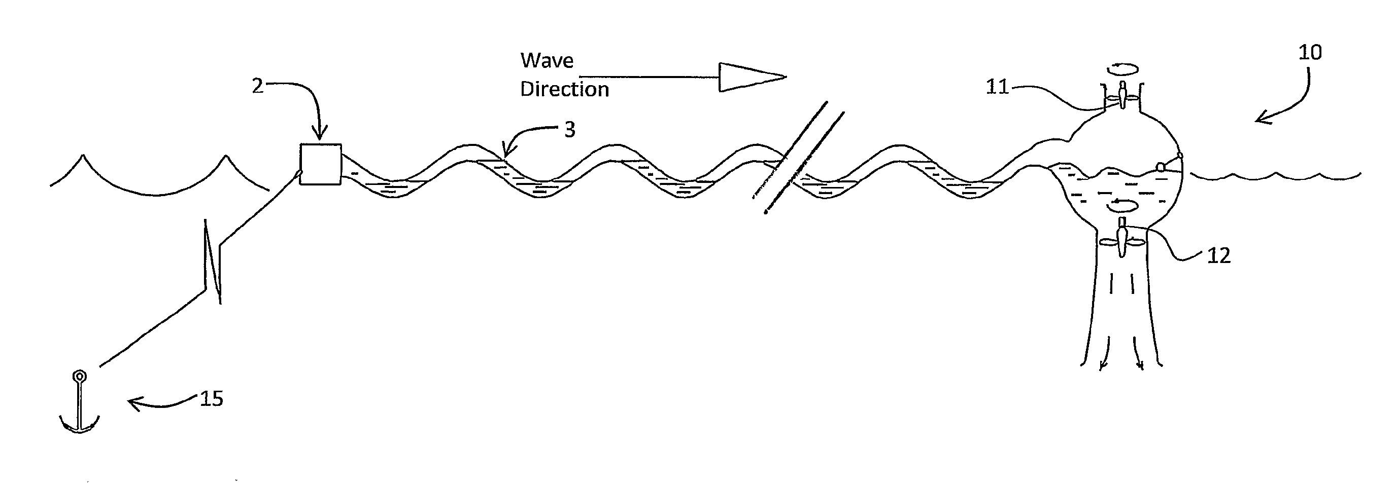
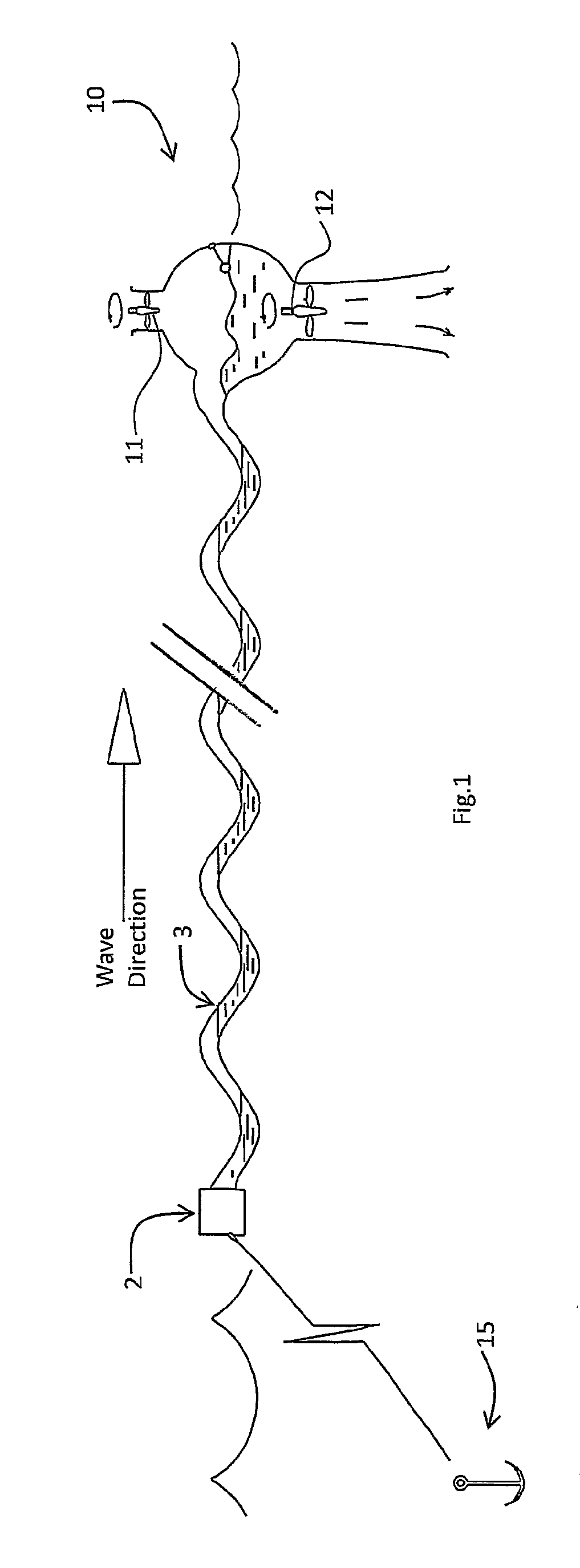
[0063]Referring to FIG. 1 a wave energy converter 1 comprises a combined air and water inlet 2 at a leading end of a flexible compressor tube 3 of approximately 250 m in length, and terminating in a power output section 10. In this embodiment, the output section 10 has an air turbine 11 using compressed air exiting the tube 3 for electricity generation, and a water turbine 12 for electricity generation from water exiting the tube under pressure. The system 1 is anchored to the sea bed by an anchor 15, however in other embodiments it may be anchored to a structure such as a wind turbine column.

[0064]The inlet 2 provides a sequence of water and air plugs. The air plugs are akin to air locks, except that they move along the tube. Wave action on the tube 3 causes pressurisation of the water and compression of the air. The output section 10 comprises a level sensor and a separator which maintain water level to control flow through the turbines.

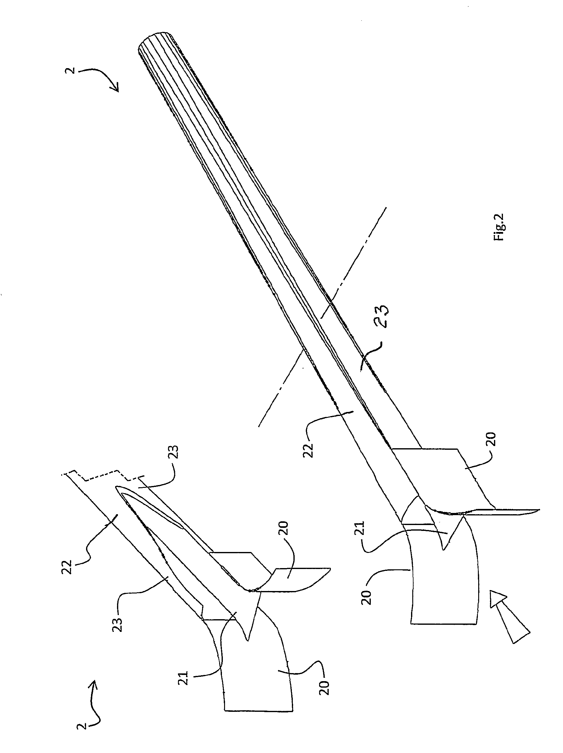
[0065]Referring to FIG. 2 the inl...


PUM


Abstract

A wave energy harnessing converter (1) has a tube (3) which floats on the sea. A water inlet (2) delivers water to the tube, and an air inlet (2) delivers air to the tube (3). The tube has sufficient buoyancy and flexibility to float on the water and conform to the shape of waves when the tube extends substantially in the direction of travel of the waves, causing water in the tube to be conveyed from the inlet and to be pressurised and the air to be compressed in a series of moving air pockets. The tube is reinforced to minimise energy losses through distortion or elongation. A converter output section (10) for receiving water and compressed air from the tube (3) for providing energy.

Description

INTRODUCTION[0001]1. Field of the Invention[0002]The invention relates to a wave energy converter.[0003]2. Prior Art Discussion[0004]The oceans contain vast amounts of concentrated energy in the form of waves but harnessing this energy economically is very difficult.[0005]A typical approach to wave energy harvesting is to provide an oscillating water column which pumps air through a turbine.[0006]WO2008 / 036141 (Catlin) describes an ocean power harvester having a network of inter-connected semi-submerged devices with air compressors.[0007]The invention is directed towards providing an improved converter and method for harvesting wave energy, which is more efficient, and / or more robust, and / or simpler.SUMMARY[0008]According to the invention, there is provided a wave energy converter comprising:[0009]at least one tube to float on the sea or other water body,[0010]a water inlet for delivering water to the tube,[0011]an air inlet for delivering air to the tube,[0012]wherein the tube has ...

Claims


Application Information

Patent Timeline
Patent Type & Authority Applications(United States)
IPC IPC(8): F04B17/00
CPCF03B13/188Y02E10/38F03B13/22F03B13/20Y02E10/30
Inventor DUFFY, PATRICK JOSEPHFITZSIMONS, JOCELYN
Owner JOSPA
Why Eureka
Try Eureka