Fuel cell device

a fuel cell and fuel cell technology, applied in the field of solid oxide fuel cell devices, can solve the problems of reduced air, reduced driving potential of the cell, and limited scalability of the sofc tube,

Inactive Publication Date: 2011-05-19
DEVOE ALAN +1
View PDF49 Cites 43 Cited by
  • Summary
  • Abstract
  • Description
  • Claims
  • Application Information

AI Technical Summary

Benefits of technology

[0019]The present invention provides a fuel cell device in which the input gas passages are separate from the exhaust gas passages. To that end, the fuel cell device comprises a solid ceramic support structure having at least one active cell therein, with each active cell comprising a first porous electrode and a second porous electrode separated by an electrolyte layer that is monolithic with the solid ceramic support structure and each of the first and second porous electrodes have a surface that forms an interface with the electrolyte layer. One or more first and second gas input passages extend within the respective first and second porous electrodes, within the electrolyte layer, and / or at the surface that forms the interface between the respective first and second porous electrodes and the electrolyte layer. Additionally, one or more first and second exhaust passages are spaced apart from the respective one or more first and second input passages, and extend within the respective first and second porous electrodes and / or at a surface thereof opposite the surface that forms the interface with the electrolyte layer. With this structure, the gases are adapted to flow from inlets in the solid ceramic support structure through the one or more first and second gas input passages to pores of the first and second porous electrodes, then through the pores of the first and second porous electrodes to the one or more first and second exhaust passages, and then through the one or more first and second exhaust passages to outlets in the solid ceramic support structure.

Problems solved by technology

A key challenge of using tubes is that you must apply both heat and air to the outside of the tube; air to provide the O2 for the reaction, and heat to accelerate the reaction.
Usually, the heat would be applied by burning fuel, so instead of applying air with 20% O2 (typical), the air is actually partially reduced (partially burned to provide the heat) and this lowers the driving potential of the cell.
An SOFC tube is also limited in its scalability.
Each tube is a single electrolyte layer, such that increases are bulky.
The solid electrolyte tube technology is further limited in terms of achievable electrolyte thinness.
Electrolyte thickness of 2 μm or even 1 μm would be optimal for high power, but is very difficult to achieve in solid electrolyte tubes.
Practically, however, total efficiency would be less than 100%, even if fuel utilization was 100%, because of various other inefficiencies and system losses.
A challenge for fuel utilization at the anode is to move molecules of fuel into the pores of the anode.
Another challenge is to move the waste products, i.e., water and CO2 molecules, out of the pores of the anode.
If the pores are too small, then the flow of fuel inward and waste-products outward will be too slow to allow high fuel utilization.
Because air is only 20% oxygen, and has 80% nitrogen, there is a challenge to move oxygen into the pores and N2 out of the pores.
One problem for gas utilization is that air and fuel can pass through the flow paths past the porous anodes and cathodes without the molecules ever entering the pores.
Additionally, if the gas molecules can't get into and out of the anode and cathode, then the fuel cell will not achieve its maximum power.
A lack of fuel or oxygen at the anodes or cathodes essentially means that the fuel cell is starved for chemical energy.
Thus, there is a high likelihood of fuel molecules passing through the large fuel passage without ever entering the pores of the anode.
In that case, the problem could be worse because the fuel is contained within the furnace volume, which is even larger than the volume within the tube.

Method used


Image

  • Fuel cell device
  • Fuel cell device
  • Fuel cell device

Examples


Embodiment Construction

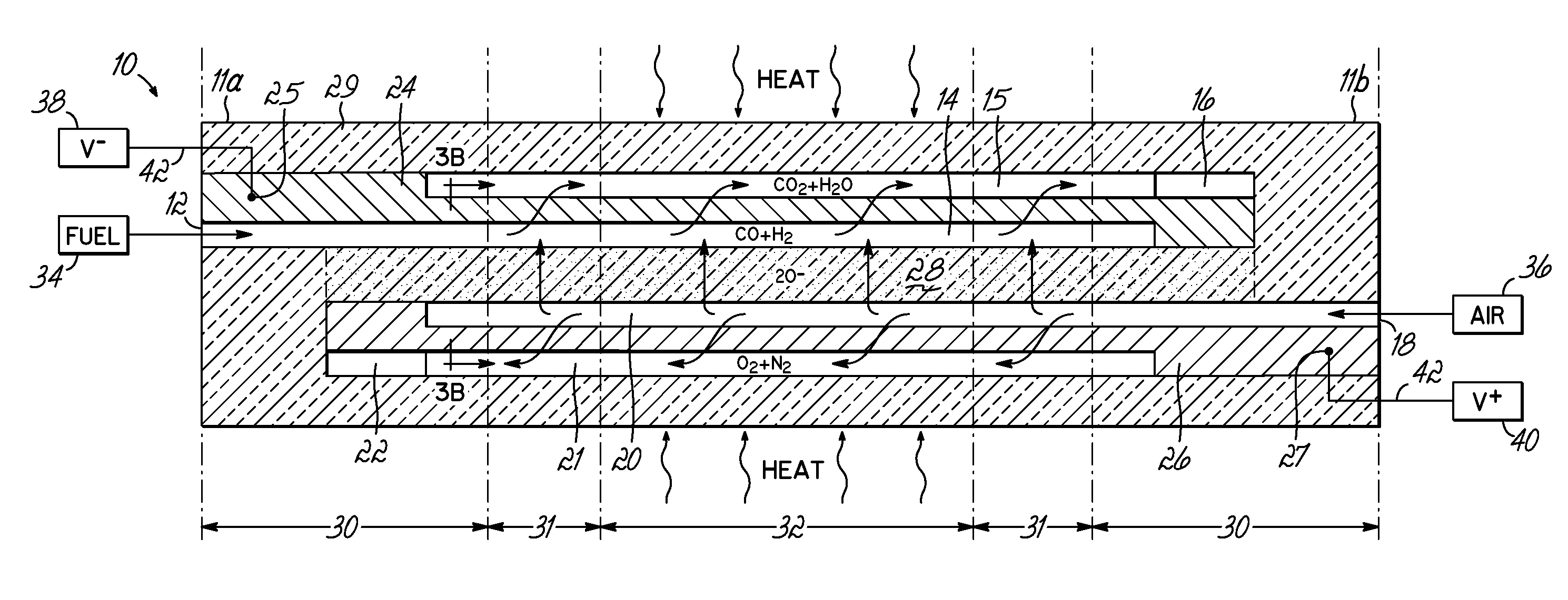
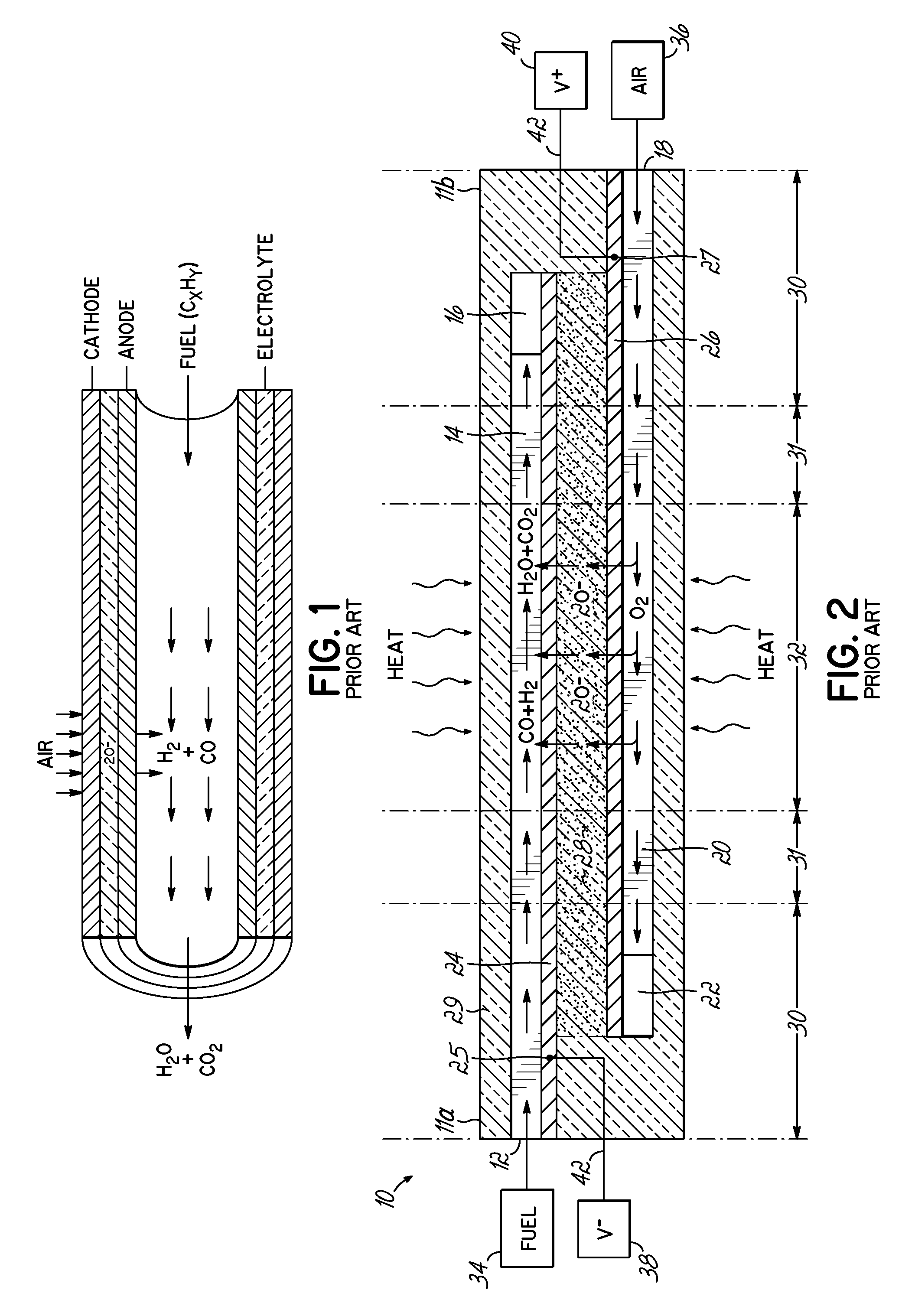
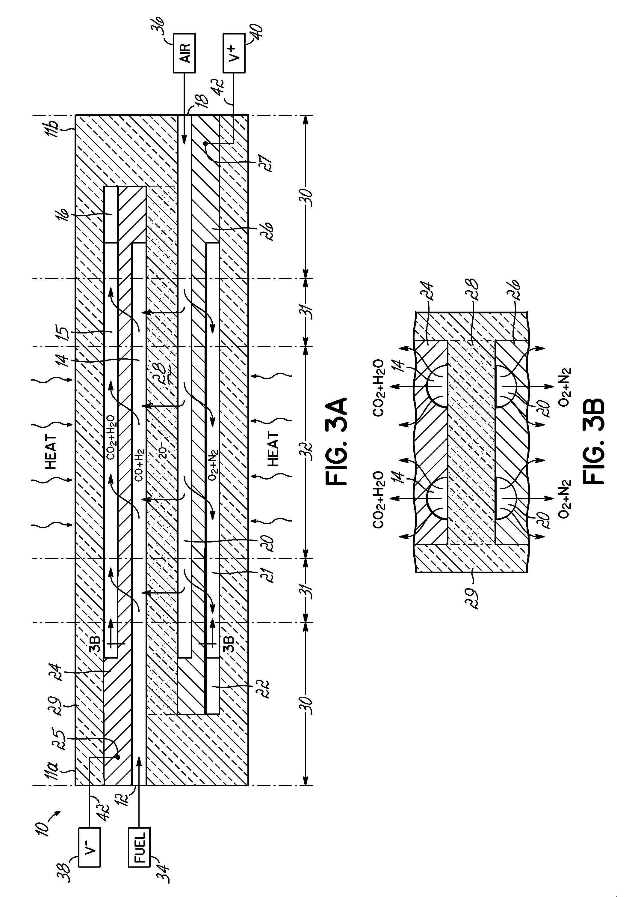
[0042]One embodiment of the invention is directed to fuel cell structure for forcing reactant gas through a porous anode or cathode, in order to make use of the fresh reactants, while flushing out the waste products. To that end, the fuel cell design separates the gas input paths to the pores from the waste output paths from the pores. Without wishing to be bound by theory, it is believed that the presence of the waste products on the fuel side (H2O, CO2) reduces the potential (the voltage that is across the electrolyte) of the cell, so that better removal of CO2 and H2O will give higher voltages and corresponding higher outputs.

[0043]Reference may be made to the following publications by the same inventors, which describe various embodiments of a multilayer Fuel Cell Stick™ device 10 (et al.), the contents of which are incorporated herein by reference: U.S. Patent Application Publication Nos. 2007 / 0104991, 2007 / 0105003, 2007 / 0111065, 2007 / 0105012, 2008 / 0171237, 2007 / 0264542 and 200...


PUM

PropertyMeasurementUnit
thicknessaaaaaaaaaa
thicknessaaaaaaaaaa
thicknessaaaaaaaaaa

Abstract

A fuel cell device is provided in which the gas input passages are separate from the exhaust gas passages to provide better flow of reactants through the pores of the electrodes. First and second porous electrodes are separated by an electrolyte layer that is monolithic with a solid ceramic support structure for the device. First and second input passages extend within the respective electrodes, within the electrolyte layer, and/or at the surfaces that form the interface between the respective electrodes and the electrolyte layer. First and second exhaust passages are spaced apart from the input passages, and extend within the respective electrodes and/or at a surface thereof opposite the interface surface with the electrolyte layer. Gases are adapted to flow through the respective input passages, then through the pores of the porous electrodes, and then through the respective exhaust passages.

Description

CROSS-REFERENCE TO RELATED APPLICATIONS[0001]Pursuant to 37 C.F.R. §1.78(a)(4), the present application claims the benefit of and priority to co-pending Provisional Application Ser. No. 61 / 261,573 (Attorney Docket No. DEVOFC-15P) filed on Nov. 16, 2009 and entitled “Fuel Cell Device and System,” which is expressly incorporated herein by reference.[0002]The present application is also related to co-pending U.S. patent application Ser. Nos. 12 / 607,384, 12 / 399,732, 12 / 267,439 and 12 / 117,622 (Attorney Docket Nos. DEVOFC-13US, DEVOFC-09US, DEVOFC-06US and DEVOFC-05US1, respectively), filed Oct. 28, 2009, Mar. 6, 2009, Nov. 7, 2008, and May 8, 2008, respectively, and each entitled “Fuel Cell Device and System,” the disclosures of which are incorporated herein by reference in their entirety. The present application is also related to co-pending U.S. patent application Ser. Nos. 11 / 747,066 and 11 / 747,073 (Attorney Docket Nos. DEVOFC-03US1 and DEVOFC-03US2), both filed on May 10, 2007 and en...

Claims


Application Information

Patent Timeline
Patent Type & Authority Applications(United States)
IPC IPC(8): H01M8/04H01M8/24
CPCH01M4/8626H01M8/0236H01M8/0256H01M8/026Y02E60/525H01M8/0271H01M8/1226H01M8/2435Y02E60/521H01M8/0265H01M8/2483Y02E60/50H01M4/86H01M8/02H01M8/12H01M8/24
Inventor DEVOE, ALANDEVOE, LAMBERT
Owner DEVOE ALAN
Why Eureka
Try Eureka