
Radio communication system, radio communication device, and radio communication method

a radio communication system and radio communication technology, applied in the field of radio communication systems, radio communication devices and radio communication methods, can solve problems such as schedulers that cannot function effectively, receive quality deterioration, and receive quality deterioration, so as to avoid transmission delay and high receiving quality

Inactive Publication Date: 2011-05-19
KYOCERA CORP
View PDF4 Cites 16 Cited by
  • Summary
  • Abstract
  • Description
  • Claims
  • Application Information

AI Technical Summary

Benefits of technology

The present invention provides a radio communication system, device, and method that allows a scheduler to function effectively while prioritizing retransmission data transmission. By setting priorities for each reception device and allocating radio resources accordingly, the system can avoid delay in transmission of data to a reception device with higher priority. Additionally, the invention includes a size determination unit to determine the size of each piece of data to be transmitted based on the priority settings. The technical effects of the invention include improved error correction capability, efficient use of radio resources, and effective prioritization of retransmission data transmission.

Problems solved by technology

However, the conventional method of transmitting retransmission data with first priority has the following problem.
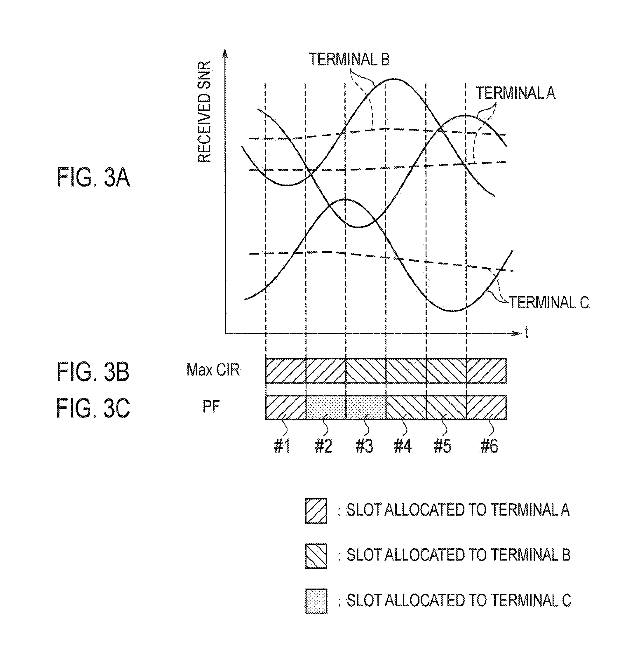
Although the scheduler sets a high priority for a reception device of high receiving quality as mentioned earlier, receiving quality is unstable in radio communication, and the receiving quality may be deteriorated at the delayed point of transmission of the transmission data.
In other words, if retransmission data is always transmitted with first priority, there is a problem that the scheduler may not function effectively.
In particular, since a radio communication system employing HARQ is configured to actively perform retransmission in expectation of improvement in error correction capability, retransmission is performed frequently and the problem becomes prominent.

Method used


Image

  • Radio communication system, radio communication device, and radio communication method
  • Radio communication system, radio communication device, and radio communication method
  • Radio communication system, radio communication device, and radio communication method

Examples


Embodiment Construction

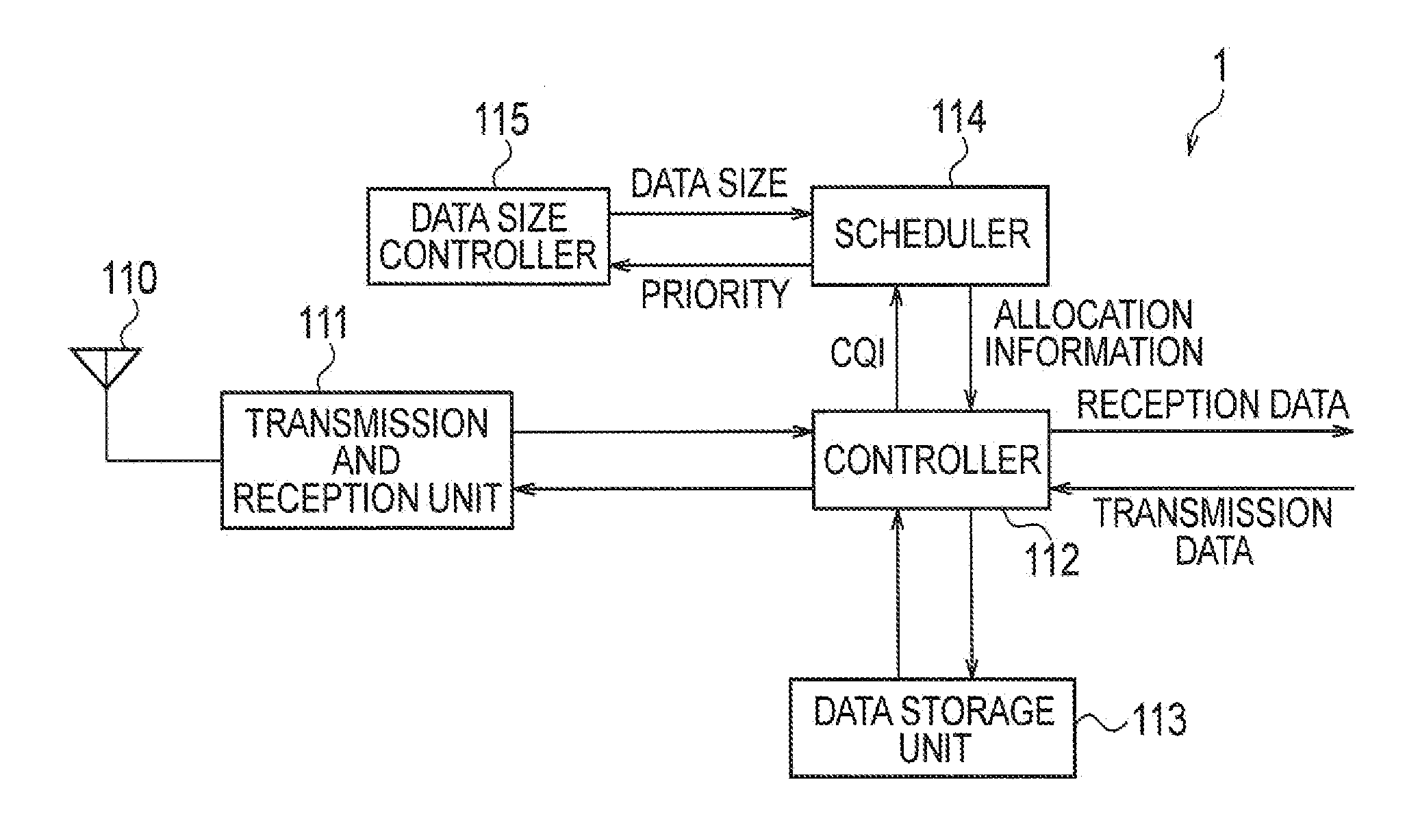
[0032]Next, a radio communication system according to an embodiment of the present invention will be described with reference to the drawings. Specifically, descriptions will be given of (1) an overall schematic configuration of the radio communication system, (2) a configuration of a radio base station, (3) an example of priority setting processing, (4) an example of data size determination and adjustment processing, (5) an operation of the radio base station, (6) advantageous effects, and (7) other embodiments. In the following descriptions of the drawings in the embodiments, the same or similar reference numerals are given to the same or similar parts.

(1) Overall Schematic Configuration of Radio Communication System

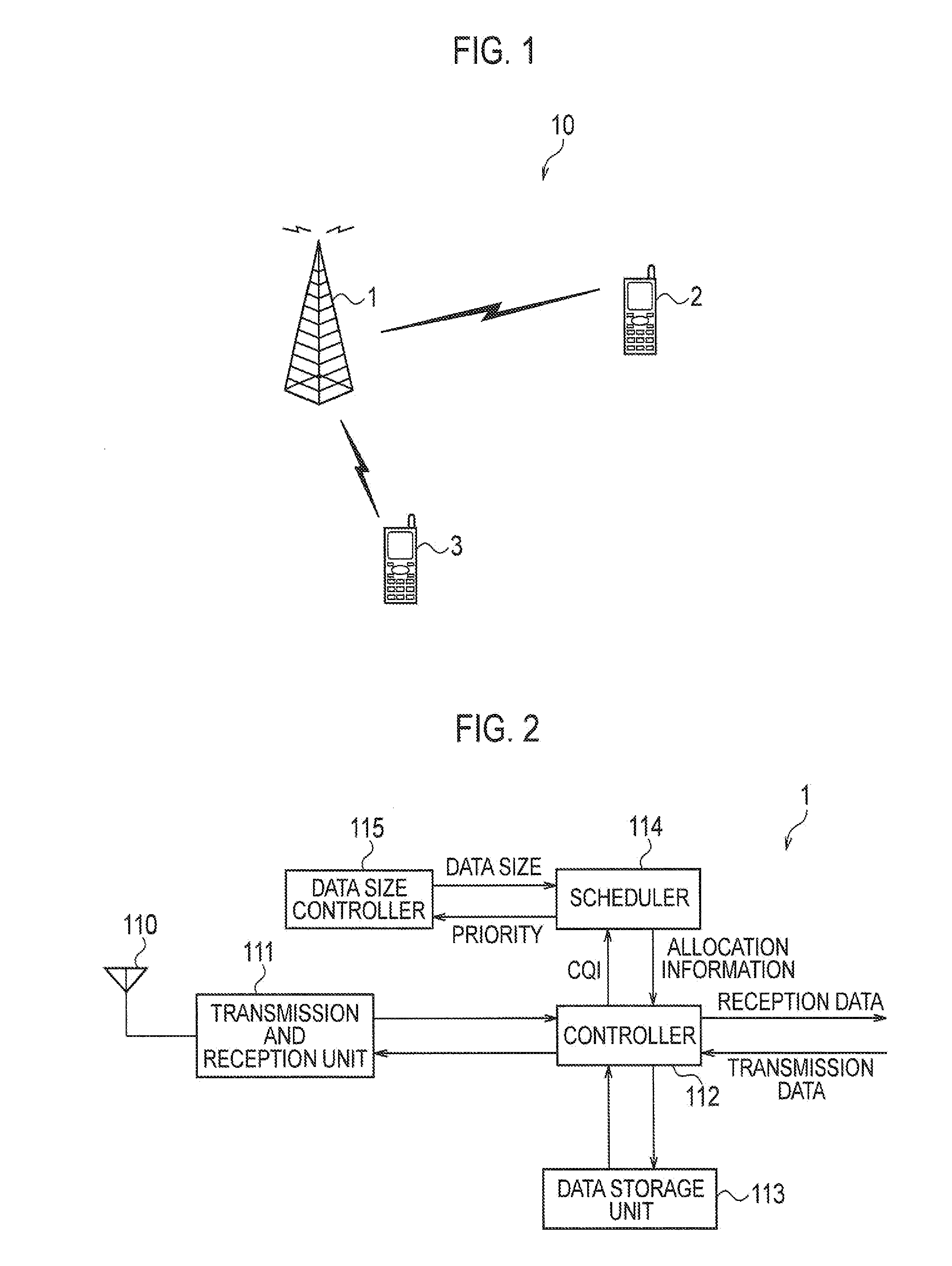
[0033]FIG. 1 is an overall schematic configuration diagram of a radio communication system 10 according to this embodiment. As shown in FIG. 1, the radio communication system 10 includes a radio base station 1, a radio terminal 2 and a radio terminal 3.

[0034]The radio ...


PUM


Abstract

A radio base station (1) includes a scheduler (114) and a control unit (112). As a reception device has a higher reception quality, the scheduler (114) sets a higher allocation priority of a radio resourse used for data transmission. When the priority β set for a transmission destination reception device by the scheduler (114) is higher than the priority α set for transmission destination reception device, the controller (112) allocates the radio resourse to both of the transmission destination reception device and the transmission destination reception device ant transmits both of the transmission data and the retransmission data by using the allocated radio resourse.

Description

TECHNICAL FIELD[0001]The present invention relates to a radio communication system, radio communication device and radio communication method to which hybrid automatic repeat request is applied.BACKGROUND ART[0002]Generally, transmission errors occur more frequently in a radio communication system than in a wireline communication system. To ensure reliability in communication in such a radio communication system, hybrid automatic repeat request (HARQ) in which both of automatic repeat request (ARQ) and forward error correction (FEC) are used is widely employed in recent years.[0003]In HARQ, in a case where a reception-side radio communication device (called reception device below) fails to decode data received from a transmission-side radio communication device (called transmission device below), the reception device transmits a retransmission request to the transmission device. Upon receipt of the retransmission request, the transmission device transmits the already-transmitted tra...

Claims


Application Information

Patent Timeline
Patent Type & Authority Applications(United States)
IPC IPC(8): H04W72/10
CPCH04L1/0003H04L1/0007H04L1/0013H04L1/0026H04W72/1242H04L1/1812H04L1/1887H04W28/04H04W72/04H04L1/0057H04W72/569
Inventor JOKO, SHINGO
Owner KYOCERA CORP
Learn More